10
5 Disassembly and Assembly Instructions
5.1.
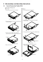
How to Remove the Flexible PCB
Front Panel
Front Panel
FFC (CNP3)
Connector
Cover
Plate
4. Disconnect the FPC Ass'y from CN452 on the TFT
PCB (E-9939A)
.
CN452
FPC Ass'y
CN707
Front Panel
Slide Mechanism
Ass'y
(Monitor Ass'y)
Monitor
Disassembly of Display Unit
. Remove the two screws( ) from the Front Panel.
2. After removing the screw ( ) from the bottom side, remove
the Connector Cover.
3. Disconnect the FFC (CNP3), which is connected to
the Front Panel, from CN707 on the Main PCB (E-3173Aa).
1. Pull out the Monitor to the arrow direction.
2. After removing the two screws ( ) and one screw ( ),
remove the Plate.
3. After removing the four screws ( ), remove the Monitor Ass'y.
4.Remove the Front Panel.
Front Panel
Monitor
Summary of Contents for CQ-VD5005W
Page 9: ...9 4 2 3 DVD Servo Block IC104 YESAM370 IC105 YESAM294 IC107 YESAM364 IC301 YESAM405 ...
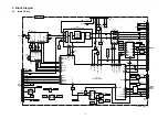
Page 16: ...16 8 Schematic Diagram 8 1 Main 1 Block ...
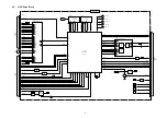
Page 17: ...17 8 2 Main 2 Block ...
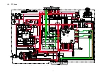
Page 18: ...18 8 3 TFT Block ...
Page 19: ...19 8 4 SW Block ...
Page 21: ...21 9 Printed Circuit Board 9 1 Main Block Top View ...
Page 22: ...22 9 2 Main Block Bottom View ...
Page 23: ...23 9 3 TFT Block Top View ...
Page 24: ...24 9 4 TFT Block Bottom View ...
Page 25: ...25 9 5 SW Block ...
Page 26: ...26 9 6 DVD Servo Block Top view ...
Page 27: ...27 9 7 DVD Servo Block Bottom View ...
Page 43: ...43 11 Schematic Diagram for Printing with A4 Size 11 1 Main 1 Block Left Side ...
Page 44: ...44 11 2 Main 1 Block Right Side ...
Page 45: ...45 11 3 Main 2 Block Left Side ...
Page 46: ...46 11 4 Main 2 Block Right Side ...
Page 47: ...47 11 5 TFT Block Left Side ...
Page 48: ...48 11 6 TFT Block Right Side ...
Page 49: ...49 11 7 SW Block Left Side ...
Page 50: ...50 11 8 SW Block Right Side ...


