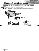
background image

6

7

CQ-VX220W

English

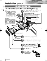
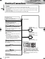
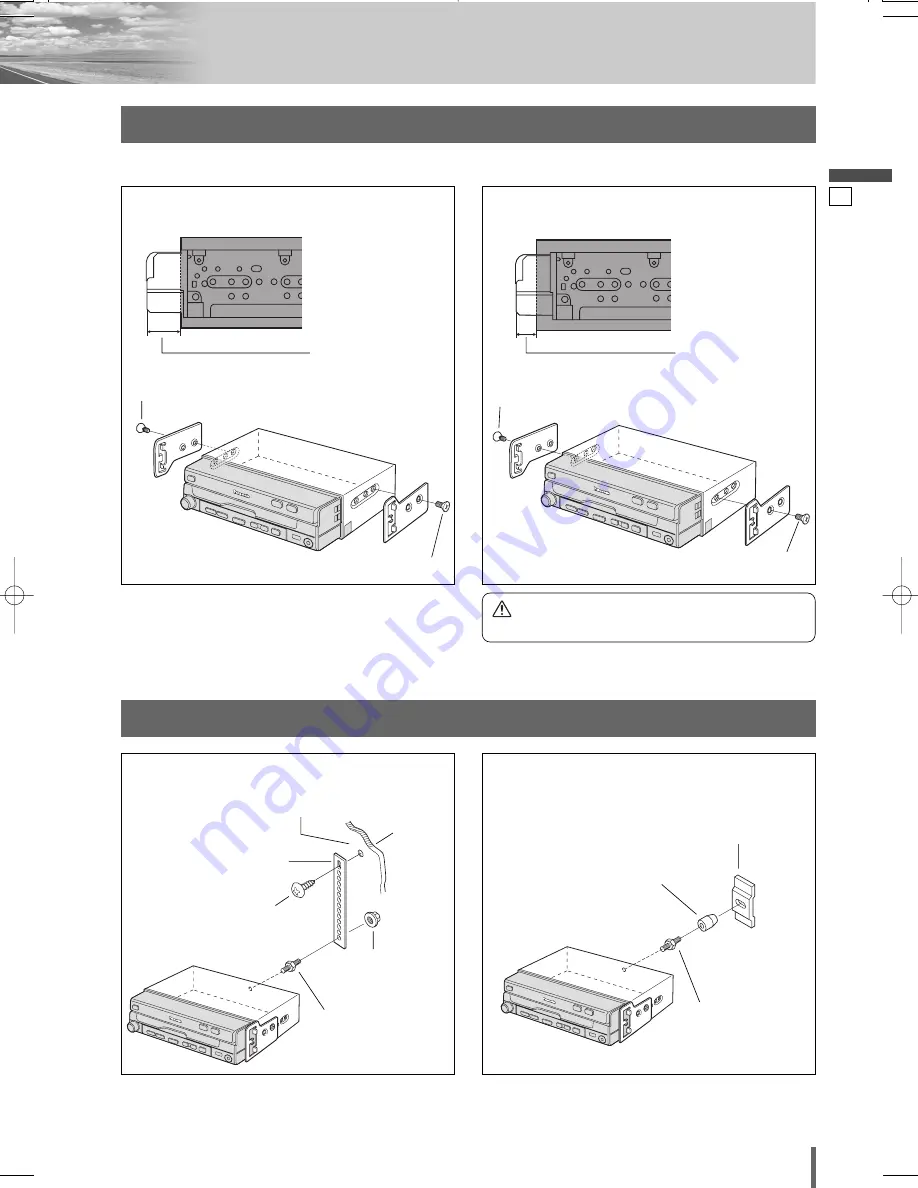
Two holes of the mounting spring allow you to select between two mounting types as shown below.

A few millimeters of 
console projecting

Less projecting

Method for Fixing the Rear of the Unit

Method for Fixing the Mounting Spring

(A) Regular installation method

(B) Deeper installation method

y

Flat-Head Screw

y

Flat-Head Screw

y

Flat-Head Screw

y

Flat-Head Screw

(a) Using the Rear Support Strap (option)

(b) Using the Rubber Cushion (option)

Fire wall of car

mm

ø

Tapping Screw 

(5 mmø x 16 mm)

(option, XTT5+16AFN)

Rear Support Strap

(option, YEFG044C002)

r

Mounting Bolt
(5 mmø)

r

Mounting Bolt
(5 mmø)

Rear Support Bracket
(Provided on the Car)

Rubber Bushing
(option)

Hex. Nut
(5 mmø)
(option, YEJN99023)

Caution

¡

Method (B) is not available in some types of cars.

VX220W̲II̲01̲eng.qxd  09.2.24  7:21 PM  ページ7

Summary of Contents for CQ-VX220W

Page 1: ...reen External Amplifier Control Power Lead Blue white stripe Power Lead Red Yellow Battery Lead Ground Lead Black Audio Video Input Terminal AV2 IN AV2 IN R Red L White R Red L White Yellow R Red L Wh...

Page 2: ...Caution PLEASE FOLLOW THE LAWS AND REGULATIONS OF YOUR STATE PROVINCE OR COUNTRY FOR INSTALLATION OF THE UNIT TO REDUCE THE RISK OF FIRE OR ELECTRIC SHOCK OR PRODUCT DAMAGE DO NOT EXPOSE THIS APPLIANC...

Page 3: ...rade Options 3 Installation 4 Electrical Connections 10 Contents Main Unit CQ VX220W Hands Free Kit with Audio Streaming featuring Bluetooth technology Bluetooth unit CY BT200N option Rear Monitor Fro...

Page 4: ...a page 10 17 Failure to do so may result in damage to the unit 3 Connect the power lead after all other connections are made 4 Be sure to connect the battery lead yellow to the pos itive terminal of...

Page 5: ...ce Accessories and their parts numbers are subject to modification without prior notice due to improvements Use the supplied screws for installation exclusively In case of losing any of them please or...

Page 6: ...t Head Screw 5 mm x 6 mm Note The car model installation condi tions and combination of the units used may impose some restric tions on opening and closing the monitor as well as on the angle and posi...

Page 7: ...ethod B Deeper installation method y Flat Head Screw y Flat Head Screw y Flat Head Screw y Flat Head Screw a Using the Rear Support Strap option b Using the Rubber Cushion option Fire wall of car 3 mm...

Page 8: ...d manufacturing year Please consult your nearest dealer or installer Select mounting screws according to the hole positions and hole shape of the bracket y Flat Head Screw 5 mm x 6 mm 4 pieces u Round...

Page 9: ...f the side brake parking brake lever Connecting the Side Brake Parking Brake Connection Lead Hand brake Foot brake Side Brake Parking Brake Connection Lead Bright green When the side brake parking bra...

Page 10: ...Left Green Rear Left Green black stripe External Amplifier Control Power Lead Blue white stripe To an external amplifier Note Use the power control lead of the TV tuner for TV tuner connection Connec...

Page 11: ...3W option Please do not connect other device to this connector CQ VX220W Rear This book refers to connections to the Panasonic car navigation system that will come onto the market in the future Descri...

Page 12: ...with a clear lens that lights when the trans mission gear is shifted into the reverse posi tion Note Connect the reverse lead after cutting the ter minal at the end Use a Reverse Extension Cord optio...

Page 13: ...s of the connecting devices are and where each of them is connected to in order to establish a proper connection VIDEO OUT COLOR LCD MONITOR VM1500 Panasonic STAND BY R ON G RCA Cord option Video Yell...

Page 14: ...upplied with CY TUP133W CY TUN133W System up Connector supplied with CY TUP133W CY TUN133W 0 Power Connector Power Connector supplied with CY TUP133W CY TUN133W External Amplifier Control Power Lead N...

Page 15: ...arrangement can be connected to the AV 1 IN terminal See Fig 1 Use of the supplied Conversion Cable for AV 1 IN or an audio pin jack that has the same electrode arrangement also allows users to enjoy...

Page 16: ...evices in addition Please observe what shapes the connectors of the connecting devices are and where each of them is connected to in order to establish a proper connection INTELLIGENT SYSTEM BS G CODE...

Page 17: ...dition Please observe what shapes the connectors of the connecting devices are and where each of them is connected to in order to establish a proper connection System up Connector supplied with CY BT2...

Page 18: ...34 CQ VX220W Memorandum...

Page 19: ...35 CQ VX220W...

Page 20: ...YFM294C151CA PTW1208 1029 Printed in China Installation Instructions Web Site http panasonic net...

Reviews: