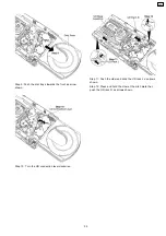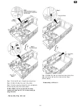
Step 4: Remove the plunger lever in 90° position.
7.1.6. Disassembly of Motor Unit
·
Follow the (Step 1) to (Step 13) of item 7.1.1. (Disassembly
of UD Base Assembly)
·
Follow the (Step 1) to (Step 6) of item 7.1.2. (Disassembly
of Disc Trays)
·
Follow the (Step 1) to (Step 16) of item 7.1.3. (Disassembly
of CD Loading Unit)
·
Follow the (Step 1) to (Step 4) of item 7.1.4. (Disassembly
of CD Loading P.C.B.)
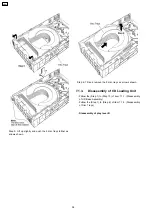
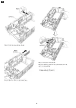
Step 1: Remove the belt.
Step 2: Push the motor unit as arrow show to remove it.
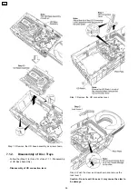
7.1.7. Disassembly of Traverse Unit
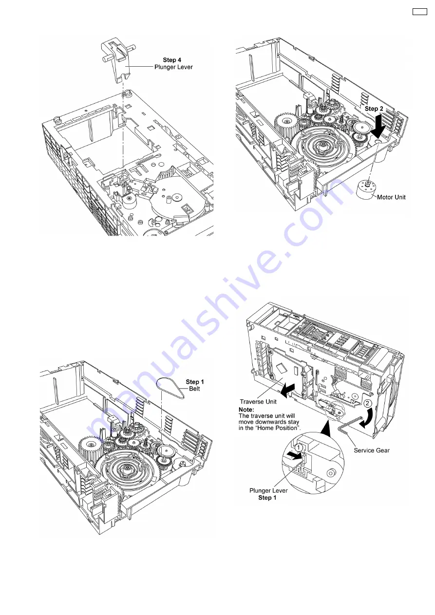
Important notes: Ensure all the trays are in the “STOCK”
position before proceeding to the disassemble of traverse
unit. For procedures to set the trays in “STOCK” position,
please refer to (5. Troubleshooting Explorer)
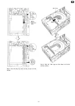
Step 1: Press and hold the plunger lever and rotate the
gear as arrows shown until it stop.
69
CRS1
Summary of Contents for CRS1
Page 3: ...1 Mechanism Overview 3 CRS1 ...
Page 28: ... For tray 1 selection flow chart below will be used 28 CRS1 ...
Page 48: ...48 CRS1 ...
Page 52: ...CRS1 52 ...
Page 97: ...12 Exploded Views 12 1 CD Loading Mechanism 97 CRS1 ...
Page 98: ...98 CRS1 ...
Page 99: ...99 CRS1 ...

