10
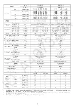
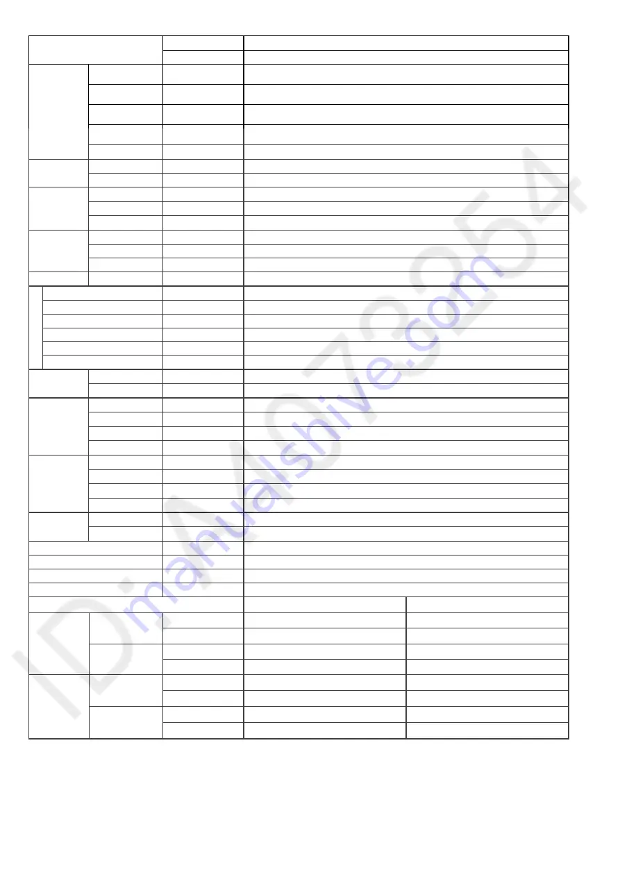
Indoor CS-A28PKD
Model
Outdoor CU-A28PKD
QLo m
3
/min (ft
3
/min)
Cooling: 15.0 (528)
Heating: 15.8 (559)
Lo m
3
/min (ft
3
/min)
Cooling: 16.2 (571)
Heating: 17.0 (602)
Me m
3
/min (ft
3
/min)
Cooling: 17.8 (628)
Heating: 17.7 (626)
Hi m
3
/min (ft
3
/min)
Cooling: 19.80 (699)
Heating: 20.40 (720)
Indoor Airflow
SHi m
3
/min (ft
3
/min)
Cooling: 20.5 (723)
Lo m
3
/min (ft
3
/min)
30.1 (1060) - 32.0 (1130)
Outdoor
Airflow
Hi m
3
/min (ft
3
/min)
52.5 (1850) - 53.5 (1890)
Control Device
Capillary Tube
Refrigerant Oil
cm
3
SUNISO 4GDID or ATMOS M60 (900)
Refrigeration
Cycle
Refrigerant Type
g (oz)
R22, 2130 (75.2)
Height (I/D / O/D)
mm (inch)
290 (11-7/16) / 750 (29-17/32)
Width (I/D / O/D)
mm (inch)
1070 (42-5/32) / 875 (34-15/32)
Dimension
Depth (I/D / O/D)
mm (inch)
240 (9-15/32) / 345 (13-19/32)
Weight
Net (I/D / O/D)
kg (lb)
12 (26) / 66 (146)
Pipe Diameter (Liquid / Gas)
mm (inch)
6.35 (1/4) / 15.88 (5/8)
Standard length
m (ft)
5.0 (16.4)
Length range (min – max)
m (ft)
3 ~ 30 (9.8 ~ 98.4)
I/D & O/D Height different
m (ft)
20.0 (65.6)
Additional Gas Amount
g/m (oz/ft)
30 (0.3)
Piping
Length for Additional Gas
m (ft)
7.5 (24.6)
Inner Diameter
mm
16.7
Drain Hose
Length mm
650
Fin Material
Aluminium (Pre coated)
Fin Type
Slit Fin
Row × Stage × FPI
2 × 15 × 21
Indoor Heat
Exchanger
Size (W × H × L)
mm
810 × 315 × 25.4
Fin Material
Aluminium (Blue coated)
Fin Type
Corrugated Fin
Row × Stage × FPI
2 × 28 × 17
Outdoor Heat
Exchanger
Size (W × H × L)
mm
44.0 × 711.2 × 802.4:836.9
Material
Polypropelene
Air Filter
Type
One-touch
Power Supply
Outdoor
Power Supply Cord
A
20
Thermostat
–
Protection Device
Inner Protector
DRY BULB
WET BULB
Maximum °C
32
23
Cooling
Minimum °C
16
11
Maximum °C
30
–
Indoor
Operation
Range
Heating
Minimum °C
16
–
Maximum °C
43
26
Cooling
Minimum °C
16
11
Maximum °C
24
18
Outdoor
Operation
Range
Heating
Minimum °C
-5
-6
1.
Cooling capacities are based on indoor temperature of 27°C Dry Bulb (80.6°F Dry Bulb), 19.0°C Wet Bulb (66.2°F Wet Bulb) and outdoor air
temperature of 35°C Dry Bulb (95°F Dry Bulb), 24°C Wet Bulb (75.2°F Wet Bulb)
2.
Heating capacities are based on indoor temperature of 20°C Dry Bulb (68°F Dry Bulb) and outdoor air temperature of 7°C Dry Bulb (44.6°F
Dry Bulb), 6°C Wet Bulb (42.8°F Wet Bulb)
3.
Specifications are subjected to change without prior notice for further improvement.
Summary of Contents for CS-A12PKD
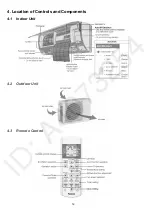
Page 12: ...12 4 Location of Controls and Components 4 1 Indoor Unit 4 2 Outdoor Unit 4 3 Remote Control...
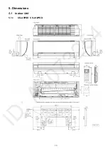
Page 13: ...13 5 Dimensions 5 1 Indoor Unit 5 1 1 CS A9PKD CS A12PKD...
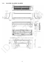
Page 14: ...14 5 1 2 CS A18PKD CS A24PKD CS A28PKD...
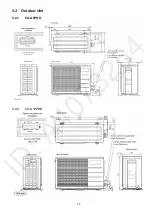
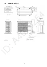
Page 15: ...15 5 2 Outdoor Unit 5 2 1 CU A9PKD 5 2 2 CU A12PKD...
Page 16: ...16 5 2 3 CU A18PKD...
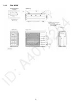
Page 17: ...17 5 2 4 CU A24PKD CU A28PKD...
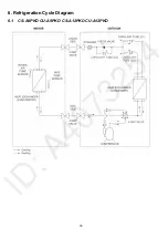
Page 18: ...18 6 Refrigeration Cycle Diagram 6 1 CS A9PKD CU A9PKD CS A12PKD CU A12PKD...
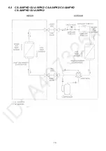
Page 19: ...19 6 2 CS A18PKD CU A18PKD CS A24PKD CU A24PKD CS A28PKD CU A28PKD...
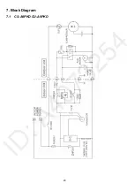
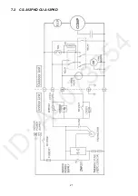
Page 20: ...20 7 Block Diagram 7 1 CS A9PKD CU A9PKD...
Page 21: ...21 7 2 CS A12PKD CU A12PKD...
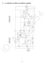
Page 22: ...22 7 3 CS A18PKD CU A18PKD CS A24PKD CU A24PKD...
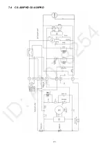
Page 23: ...23 7 4 CS A28PKD CU A28PKD...
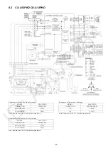
Page 28: ...28 9 Electronic Circuit Diagram 9 1 CS A9PKD CU A9PKD...
Page 29: ...29 9 2 CS A12PKD CU A12PKD...
Page 30: ...30 9 3 CS A18PKD CU A18PKD CS A24PKD CU A24PKD...
Page 31: ...31 9 4 CS A28PKD CU A28PKD...
Page 34: ...34 10 1 4 Comparator Printed Circuit Board 10 1 5 Human Activity Sensor Printed Circuit Board...
Page 40: ...40 11 2 5 Wire Stripping And Connecting Requirement...
Page 48: ...48 12 2 5 Wire Stripping And Connecting Requirement...
Page 87: ...87 Normal Deice Time Diagram Overload Deice Time Diagram...
Page 92: ...92 a Normal Deice Time Diagram b Overload Deice Time Diagram...
Page 98: ...98 Figure 3 Figure 4 17 1 1 3 To remove discharge grille Figure 5...
Page 100: ...100 Figure 9 Figure 10...
Page 104: ...104 Figure 20 Figure 21...
Page 105: ...105 18 Technical Data 18 1 Thermostat Characteristics...


