68
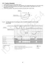
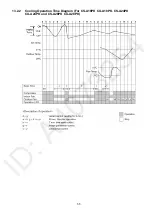
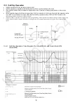
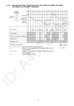
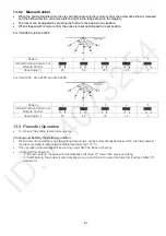
(Heating Operation condition)
•
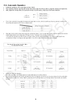
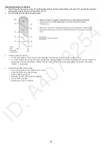
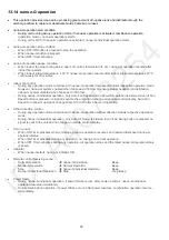
When Powerful operation is set, the setting temperature will be automatically increased 3°C against the present
setting temperature (Higher temperature: 30°C).
•
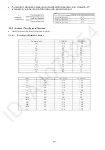
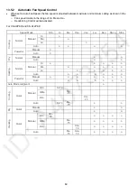
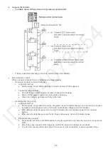
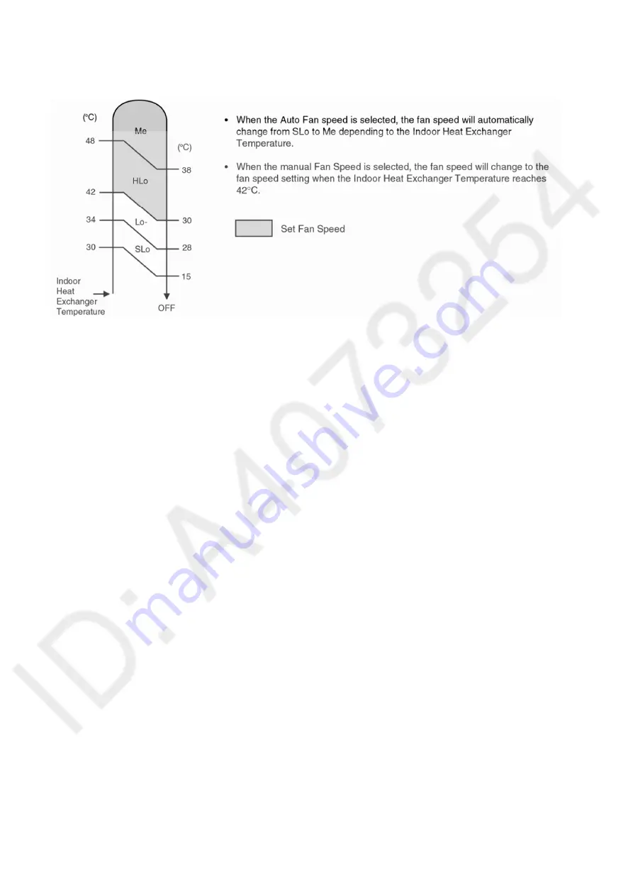
The Fan Speed will shift as shown below:
•
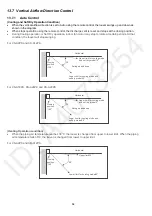
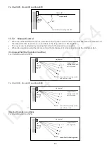
Vertical Airflow Direction:-
o
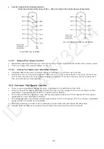
In “Manual” setting, the vane will automatically shift down 5° lower than previous setting.
o
In “Auto” setting, the vane will automatically shift between upper and lower limit depending on the intake air
temperature as Heating Mode, Airflow Direction Auto-Control. However the upper and lower limit will be
shifted 5° downward.
•
Powerful operation stops when:-
o
Powerful operation has operate for 4 hours.
o
Powerful button is pressed again.
o
Quiet button is pressed
o
Stopped by OFF/ON operation button.
o
Timer OFF activates.
o
Operating mode is changed.
Summary of Contents for CS-A12PKD
Page 12: ...12 4 Location of Controls and Components 4 1 Indoor Unit 4 2 Outdoor Unit 4 3 Remote Control...
Page 13: ...13 5 Dimensions 5 1 Indoor Unit 5 1 1 CS A9PKD CS A12PKD...
Page 14: ...14 5 1 2 CS A18PKD CS A24PKD CS A28PKD...
Page 15: ...15 5 2 Outdoor Unit 5 2 1 CU A9PKD 5 2 2 CU A12PKD...
Page 16: ...16 5 2 3 CU A18PKD...
Page 17: ...17 5 2 4 CU A24PKD CU A28PKD...
Page 18: ...18 6 Refrigeration Cycle Diagram 6 1 CS A9PKD CU A9PKD CS A12PKD CU A12PKD...
Page 19: ...19 6 2 CS A18PKD CU A18PKD CS A24PKD CU A24PKD CS A28PKD CU A28PKD...
Page 20: ...20 7 Block Diagram 7 1 CS A9PKD CU A9PKD...
Page 21: ...21 7 2 CS A12PKD CU A12PKD...
Page 22: ...22 7 3 CS A18PKD CU A18PKD CS A24PKD CU A24PKD...
Page 23: ...23 7 4 CS A28PKD CU A28PKD...
Page 28: ...28 9 Electronic Circuit Diagram 9 1 CS A9PKD CU A9PKD...
Page 29: ...29 9 2 CS A12PKD CU A12PKD...
Page 30: ...30 9 3 CS A18PKD CU A18PKD CS A24PKD CU A24PKD...
Page 31: ...31 9 4 CS A28PKD CU A28PKD...
Page 34: ...34 10 1 4 Comparator Printed Circuit Board 10 1 5 Human Activity Sensor Printed Circuit Board...
Page 40: ...40 11 2 5 Wire Stripping And Connecting Requirement...
Page 48: ...48 12 2 5 Wire Stripping And Connecting Requirement...
Page 87: ...87 Normal Deice Time Diagram Overload Deice Time Diagram...
Page 92: ...92 a Normal Deice Time Diagram b Overload Deice Time Diagram...
Page 98: ...98 Figure 3 Figure 4 17 1 1 3 To remove discharge grille Figure 5...
Page 100: ...100 Figure 9 Figure 10...
Page 104: ...104 Figure 20 Figure 21...
Page 105: ...105 18 Technical Data 18 1 Thermostat Characteristics...

