95
16. Troubleshooting
Guide
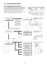
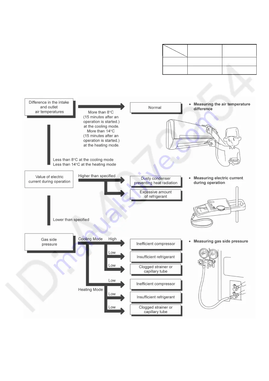
16.1 Refrigeration cycle system
In order to diagnose malfunctions, make sure that there are no
electrical problems before inspecting the refrigeration cycle.
Such problems include insufficient insulation, problem with the
power source, malfunction of a compressor and a fan.
The normal outlet air temperature and pressure of the
refrigeration cycle depends on various conditions, the standard
values for them are shown in the table on the right.
Normal Pressure and Outlet Air Temperature (Standard)
Gas Pressure
Mpa
(kg/cm
2
G)
Outlet air
Temperature
(°C)
Cooling Mode
0.4 ~ 0.6 (4 ~ 6)
12 ~ 16
Heating Mode 1.5 ~ 2.1 (15 ~ 21)
36 ~ 45
Condition: Indoor fan speed = High
Outdoor temperature 35°C at the cooling
mode and 7°C at the heating mode
Summary of Contents for CS-A12PKD
Page 12: ...12 4 Location of Controls and Components 4 1 Indoor Unit 4 2 Outdoor Unit 4 3 Remote Control...
Page 13: ...13 5 Dimensions 5 1 Indoor Unit 5 1 1 CS A9PKD CS A12PKD...
Page 14: ...14 5 1 2 CS A18PKD CS A24PKD CS A28PKD...
Page 15: ...15 5 2 Outdoor Unit 5 2 1 CU A9PKD 5 2 2 CU A12PKD...
Page 16: ...16 5 2 3 CU A18PKD...
Page 17: ...17 5 2 4 CU A24PKD CU A28PKD...
Page 18: ...18 6 Refrigeration Cycle Diagram 6 1 CS A9PKD CU A9PKD CS A12PKD CU A12PKD...
Page 19: ...19 6 2 CS A18PKD CU A18PKD CS A24PKD CU A24PKD CS A28PKD CU A28PKD...
Page 20: ...20 7 Block Diagram 7 1 CS A9PKD CU A9PKD...
Page 21: ...21 7 2 CS A12PKD CU A12PKD...
Page 22: ...22 7 3 CS A18PKD CU A18PKD CS A24PKD CU A24PKD...
Page 23: ...23 7 4 CS A28PKD CU A28PKD...
Page 28: ...28 9 Electronic Circuit Diagram 9 1 CS A9PKD CU A9PKD...
Page 29: ...29 9 2 CS A12PKD CU A12PKD...
Page 30: ...30 9 3 CS A18PKD CU A18PKD CS A24PKD CU A24PKD...
Page 31: ...31 9 4 CS A28PKD CU A28PKD...
Page 34: ...34 10 1 4 Comparator Printed Circuit Board 10 1 5 Human Activity Sensor Printed Circuit Board...
Page 40: ...40 11 2 5 Wire Stripping And Connecting Requirement...
Page 48: ...48 12 2 5 Wire Stripping And Connecting Requirement...
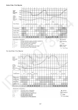
Page 87: ...87 Normal Deice Time Diagram Overload Deice Time Diagram...
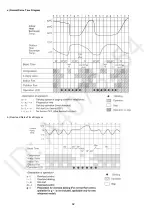
Page 92: ...92 a Normal Deice Time Diagram b Overload Deice Time Diagram...
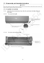
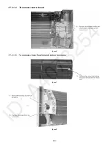
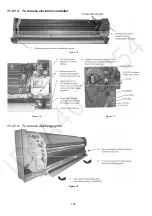
Page 98: ...98 Figure 3 Figure 4 17 1 1 3 To remove discharge grille Figure 5...
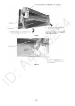
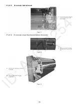
Page 100: ...100 Figure 9 Figure 10...
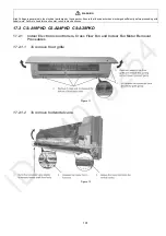
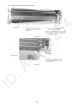
Page 104: ...104 Figure 20 Figure 21...
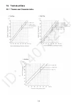
Page 105: ...105 18 Technical Data 18 1 Thermostat Characteristics...

