© Panasonic HA Air-Conditioning (M) Sdn. Bhd. 2010.
Unauthorized copying and distribution is a violation of law.
Order No. PHAAM1001025C2
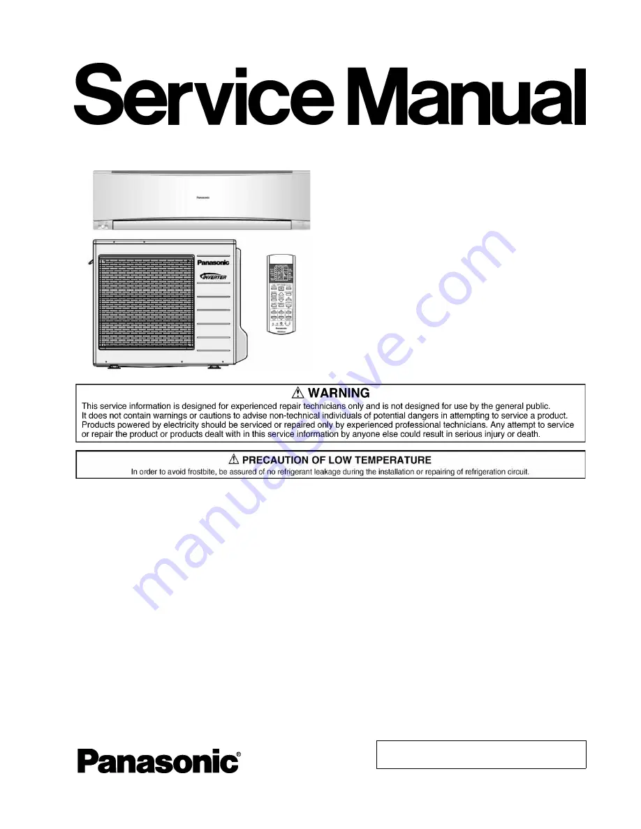
Air Conditioner
Indoor Unit
Outdoor Unit
CS-E24LKES CU-E24LKE
CS-E28LKES CU-E28LKE
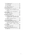
TABLE OF CONTENTS
PAGE
PAGE
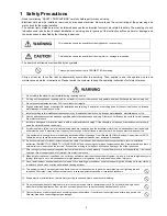
1 Safety Precautions
-----------------------------------------------
3
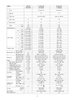
2 Specifications
-----------------------------------------------------
5
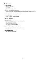
3 Features
-------------------------------------------------------------
8
4 Location of Controls and Components
-------------------
9
4.1. Indoor Unit--------------------------------------------------- 9
4.2. Outdoor Unit ------------------------------------------------ 9
4.3. Remote Control -------------------------------------------- 9
5 Dimensions
--------------------------------------------------------
10
5.1. Indoor Unit & Remote Control -------------------------10
5.2. Outdoor Unit ----------------------------------------------- 11
6 Refrigeration Cycle Diagram
--------------------------------
12
7 Block Diagram
----------------------------------------------------
13
8 Wiring Connection Diagram
---------------------------------
14
8.1. Indoor Unit--------------------------------------------------14
8.2. Outdoor Unit -----------------------------------------------15
9 Electronic Circuit Diagram
-----------------------------------
17
9.1. Indoor Unit ------------------------------------------------- 17
9.2. Outdoor Unit----------------------------------------------- 18
10 Printed Circuit Board
------------------------------------------
20
10.1. Indoor Unit ------------------------------------------------- 20
10.2. Outdoor Unit----------------------------------------------- 23
11 Installation Instruction
----------------------------------------
25
11.1. Select the Best Location ------------------------------- 25
11.2. Indoor Unit ------------------------------------------------- 26
11.3. Outdoor Unit----------------------------------------------- 29
12 Operation and Control
----------------------------------------
32
12.1. Basic Function -------------------------------------------- 32
12.2. Airflow Direction ------------------------------------------ 34
12.3. Quiet operation (Cooling Mode/Cooling area
of Soft Dry Mode) ---------------------------------------- 35
12.4. Powerful Mode Operation------------------------------ 36
12.5. Timer Control---------------------------------------------- 37
Summary of Contents for CS-E24LKES
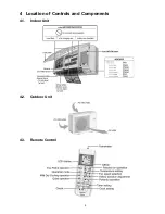
Page 9: ...9 4 Location of Controls and Components 4 1 Indoor Unit 4 2 Outdoor Unit 4 3 Remote Control ...
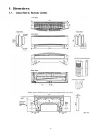
Page 10: ...10 5 Dimensions 5 1 Indoor Unit Remote Control ...
Page 11: ...11 5 2 Outdoor Unit ...
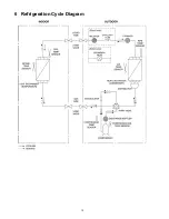
Page 12: ...12 6 Refrigeration Cycle Diagram ...
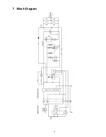
Page 13: ...13 7 Block Diagram ...
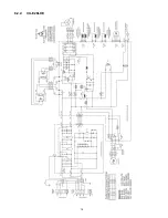
Page 14: ...14 8 Wiring Connection Diagram 8 1 Indoor Unit ...
Page 15: ...15 8 2 Outdoor Unit 8 2 1 CU E24LKE ...
Page 16: ...16 8 2 2 CU E28LKE ...
Page 17: ...17 9 Electronic Circuit Diagram 9 1 Indoor Unit ...
Page 18: ...18 9 2 Outdoor Unit 9 2 1 CU E24LKE ...
Page 19: ...19 9 2 2 CU E28LKE ...
Page 20: ...20 10 Printed Circuit Board 10 1 Indoor Unit 10 1 1 Main Printed Circuit Board ...
Page 23: ...23 10 2 Outdoor Unit 10 2 1 Main Printed Circuit Board ...
Page 24: ...24 10 2 2 Power Printed Circuit Board ...
Page 90: ...90 16 1 3 To remove power electronic controller ...
Page 91: ...91 16 1 4 To remove discharge grille 16 1 5 To remove control board ...
Page 92: ...92 16 1 6 To remove cross flow fan and indoor fan motor ...
Page 93: ...93 ...


