2
12.6. Auto Restart Control------------------------------------- 37
12.7. Indication Panel------------------------------------------- 37
12.8. Patrol Operation ------------------------------------------ 38
12.9. e-ion Operation ------------------------------------------- 40
12.10. Mild Dry Cooling Operation ---------------------------- 42
12.11. ECO Patrol Operation----------------------------------- 43
13 Protection Control
----------------------------------------------
47
13.1. Protection Control For All Operations --------------- 47
13.2. Protection Control For Cooling & Soft Dry
Operation--------------------------------------------------- 49
13.3. Protection Control For Heating Operation --------- 50
14 Servicing Mode
--------------------------------------------------
51
14.1. Auto OFF/ON Button ------------------------------------ 51
14.2. Remote Control Button --------------------------------- 52
15 Troubleshooting Guide
----------------------------------------
53
15.1. Refrigeration Cycle System --------------------------- 53
15.2. Relationship Between The Condition Of The
Air Conditioner And Pressure And Electric
Current ------------------------------------------------------ 54
15.3. Breakdown Self Diagnosis Function ---------------- 55
15.4. Error Codes Table---------------------------------------- 56
15.5. Self-diagnosis Method ---------------------------------- 59
16 Disassembly and Assembly Instructions
---------------
89
16.1. Indoor Electronic Controllers, Cross Flow Fan
and Indoor Fan Motor Removal Procedures ------ 89
16.2. Outdoor Electronic Controller Removal
Procedure -------------------------------------------------- 94
17 Technical Data
----------------------------------------------------
95
17.1. Operation Characteristics ------------------------------ 95
17.2. Sensible Capacity Chart------------------------------ 103
18 Exploded View and Replacement Parts List
---------
104
18.1. Indoor Unit ----------------------------------------------- 104
18.2. Outdoor Unit --------------------------------------------- 107
Summary of Contents for CS-E24LKES
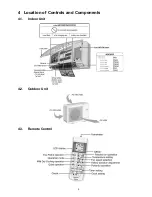
Page 9: ...9 4 Location of Controls and Components 4 1 Indoor Unit 4 2 Outdoor Unit 4 3 Remote Control ...
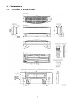
Page 10: ...10 5 Dimensions 5 1 Indoor Unit Remote Control ...
Page 11: ...11 5 2 Outdoor Unit ...
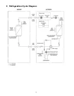
Page 12: ...12 6 Refrigeration Cycle Diagram ...
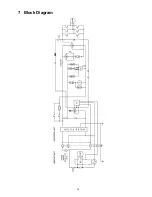
Page 13: ...13 7 Block Diagram ...
Page 14: ...14 8 Wiring Connection Diagram 8 1 Indoor Unit ...
Page 15: ...15 8 2 Outdoor Unit 8 2 1 CU E24LKE ...
Page 16: ...16 8 2 2 CU E28LKE ...
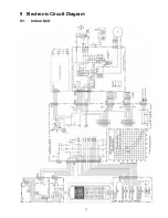
Page 17: ...17 9 Electronic Circuit Diagram 9 1 Indoor Unit ...
Page 18: ...18 9 2 Outdoor Unit 9 2 1 CU E24LKE ...
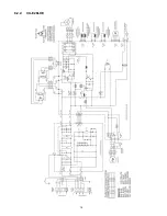
Page 19: ...19 9 2 2 CU E28LKE ...
Page 20: ...20 10 Printed Circuit Board 10 1 Indoor Unit 10 1 1 Main Printed Circuit Board ...
Page 23: ...23 10 2 Outdoor Unit 10 2 1 Main Printed Circuit Board ...
Page 24: ...24 10 2 2 Power Printed Circuit Board ...
Page 90: ...90 16 1 3 To remove power electronic controller ...
Page 91: ...91 16 1 4 To remove discharge grille 16 1 5 To remove control board ...
Page 92: ...92 16 1 6 To remove cross flow fan and indoor fan motor ...
Page 93: ...93 ...


