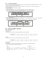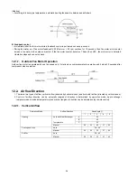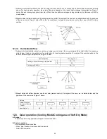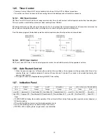
40
• Indicator
- When patrol is selected, patrol sensor indicator ON.
• Remote Control Receiving Sound
• Timer Control
- When ON timer activates when unit stops, previous operation resumes and restored last saved Patrol operation status.
- When ON timer activates during any operation, no change and carry on current operation.
- When OFF timer activates during any operation, all operation stops and the latest Patrol operation status is saved.
• Power Failure Control
- During Patrol individual operation, if power failure occurs, after power resumes, Patrol individual operation resumes
immediately.
- During combination operation, if power failure occurs, after power resumes combination operation resume immediately.
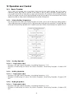
12.9. e-ion Operation
A. Purpose
This operation provides clean air by producing negative ions to attract dust captured at the positively charged e-ion filters.
B. Control Condition
a. e-ion operation start condition
• During unit running at any operation mode, if “e-ion” operation is selected, combination operation (operation mode + e-ion
operation) starts.
• During unit is OFF, if “e-ion” operation is selected, e-ion individual operation starts.
b. e-ion operation stop condition
• When “OFF/ON” button is pressed to stop the operation.
• When “PATROL/e-ion” button is pressed.
• When OFF Timer activates.
c. e-ion operation pause condition
• When indoor fan stop (during deice, odor cut control, thermostat off, etc.). e-ion operation resume after indoor fan restarts.
• When indoor intake temperature 40
°
C. e-ion operation resume after indoor intake temperature < 40
°
C continuously for 30
minutes.
C. Control Content
a. Indoor fan control
• During any operation mode combines with e-ion operation, fan speed follows respective operation mode.
• During e-ion individual operation - only Auto Fan Speed and no Powerful operation is allowed. Even if Fan Speed button is
pressed, no signal is sent to air conditioner, and no change on LCD display.
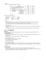
NO
Description
BLUE
E-ION
1
When patrol is selected function is not selected
OFF
-
2
During gas sensor error detection control
OFF
OFF
3
During stop
OFF
OFF
4
2 minutes gas sensor initial stabilization time (Level 0)
ON
OFF
5
During operation
During patrol
a. Dirtiness level 0*
ON
OFF
b. Dirtiness level 1
ON
OFF
c. Dirtiness level 1*
ON
ON
d. Dirtiness level 2
ON
ON
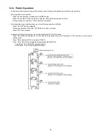
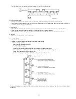
• Normal Operation
• Patrol Mode
• Patrol Mode
• Stop
→
→
→
→
Patrol Mode
Stop
Normal Operation
Patrol
:
:
:
:
Beep
Long Beep
Beep
Beep
Summary of Contents for CS-E24LKES
Page 9: ...9 4 Location of Controls and Components 4 1 Indoor Unit 4 2 Outdoor Unit 4 3 Remote Control ...
Page 10: ...10 5 Dimensions 5 1 Indoor Unit Remote Control ...
Page 11: ...11 5 2 Outdoor Unit ...
Page 12: ...12 6 Refrigeration Cycle Diagram ...
Page 13: ...13 7 Block Diagram ...
Page 14: ...14 8 Wiring Connection Diagram 8 1 Indoor Unit ...
Page 15: ...15 8 2 Outdoor Unit 8 2 1 CU E24LKE ...
Page 16: ...16 8 2 2 CU E28LKE ...
Page 17: ...17 9 Electronic Circuit Diagram 9 1 Indoor Unit ...
Page 18: ...18 9 2 Outdoor Unit 9 2 1 CU E24LKE ...
Page 19: ...19 9 2 2 CU E28LKE ...
Page 20: ...20 10 Printed Circuit Board 10 1 Indoor Unit 10 1 1 Main Printed Circuit Board ...
Page 23: ...23 10 2 Outdoor Unit 10 2 1 Main Printed Circuit Board ...
Page 24: ...24 10 2 2 Power Printed Circuit Board ...
Page 90: ...90 16 1 3 To remove power electronic controller ...
Page 91: ...91 16 1 4 To remove discharge grille 16 1 5 To remove control board ...
Page 92: ...92 16 1 6 To remove cross flow fan and indoor fan motor ...
Page 93: ...93 ...

