background image

41

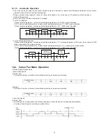
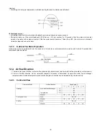
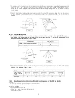
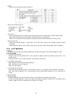
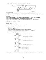
Auto Fan Speed for e-ion operation switches between HLo and CLo at pattern below:

b. Airflow direction control

• During any operation mode combines with e-ion operation, airflow direction follows respective operation mode.
• During e-ion individual operation, only Auto Air Swing is allowed. Even if Air Swing button is pressed, no signal is sent to air

conditioner, and no change on LCD display.

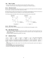
c. Timer control

• When ON timer activates when unit stops, previous operation resumes and restores last saved e-ion operation status.
• When ON timer activates during any operation, no change and carry on current operation.
• When OFF timer activates during any operation, all operation stops and the latest e-ion operation status is saved.

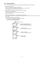
d. Indicator

• When e-ion operation starts, e-ion indicator ON.

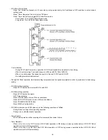
e. e-ion Check Mode

• e-ion abnormality check mode
• Purpose is to improve sensor serviceability when sensor is malfunction.

1. Control starting condition

When all of the conditions are formed

• Not in Patrol Demo mode.
• e-ion operation mode ON.
• When e-ion check mode signal is received; the procedure of selection is as shown:
- Press “Set” button continuously for 15 seconds by using pointer to enter internal setting mode.
- Press “Timer Decrement” button to select “CHC”.
- Confirm setting by pressing “Timer Set” button, a “beep” sound will be heard.

• If abnormal discharge is detected at filter (short-circuited) due to water or dust adhesion, etc., the e-ion indicator blinks

immediately.

Summary of Contents for CS-E24LKES

Page 1: ... Indoor Unit Remote Control 10 5 2 Outdoor Unit 11 6 Refrigeration Cycle Diagram 12 7 Block Diagram 13 8 Wiring Connection Diagram 14 8 1 Indoor Unit 14 8 2 Outdoor Unit 15 9 Electronic Circuit Diagram 17 9 1 Indoor Unit 17 9 2 Outdoor Unit 18 10 Printed Circuit Board 20 10 1 Indoor Unit 20 10 2 Outdoor Unit 23 11 Installation Instruction 25 11 1 Select the Best Location 25 11 2 Indoor Unit 26 11 ...

Page 2: ... Troubleshooting Guide 53 15 1 Refrigeration Cycle System 53 15 2 Relationship Between The Condition Of The Air Conditioner And Pressure And Electric Current 54 15 3 Breakdown Self Diagnosis Function 55 15 4 Error Codes Table 56 15 5 Self diagnosis Method 59 16 Disassembly and Assembly Instructions 89 16 1 Indoor Electronic Controllers Cross Flow Fan and Indoor Fan Motor Removal Procedures 89 16 2...

Page 3: ...ring standard regulation and the installation instruction An independent circuit and single outlet must be used If electrical circuit capacity is not enough or defect found in electrical work it will cause electrical shock or fire 9 This equipment is strongly recommended to be installed with Earth Leakage Circuit Breaker ELCB or Residual Current Device RCD Otherwise it may cause electrical shock a...

Page 4: ...ighten the flare nut with torque wrench according to specified method If the flare nut is over tightened after a long period the flare may break and cause refrigerant gas leakage 4 Do not touch outdoor unit air inlet and aluminium fin It may cause injury 5 Select an installation location which is easy for maintenance 6 Pb free solder has a higher melting point than standard solder typically the me...

Page 5: ...g Current A 12 1 15 0 Input Power W 360 2 66k 3 20k 360 3 30k 3 75k COP W W 2 50 3 23 3 09 2 50 2 91 2 93 Kcal hW 2 14 2 78 2 66 2 14 2 50 2 53 Power Factor 96 96 Indoor Noise H L QLo dB A 47 38 35 48 38 35 Power Level dB 63 54 51 64 54 51 Outdoor Noise H L dB A 52 53 Power Level dB 66 67 Low Temp Capacity kW I Power W COP 7 17 2 83k 2 53 7 97 3 32k 2 40 Extr Low Temp Capacity kW I Power W COP 6 1...

Page 6: ...7 16 795 31 5 16 290 11 7 16 795 31 5 16 Width I D O D mm inch 1070 42 5 32 875 34 15 32 1070 42 5 32 875 34 15 32 Depth I D O D mm inch 235 9 9 32 320 12 5 8 235 9 9 32 320 12 5 8 Weight Net I D O D kg lb 12 26 65 143 12 26 66 132 P I P I N G Pipe Diameter Liquid Gas mm inch 6 35 1 4 15 88 5 8 6 35 1 4 15 88 5 8 Standard Length m ft 5 0 16 4 5 0 16 4 Length Range min max m ft 3 9 8 30 98 4 3 9 8 ...

Page 7: ...mperature of 20 C outdoor 2 1 C 4 Heating extreme low temperature capacity Input Power and COP measured at 230 V indoor temperature of 20 C outdoor 7 8 C 5 Specifications are subjected to change without prior notice for further improvement Thermostat Electronic Control Electronic Control Protection Device Electronic Control Electronic Control Dry Bulb Wet Bulb Dry Bulb Wet Bulb Indoor Operation Ra...

Page 8: ...10A Long Installation Piping CS CU E24 28LK long piping up to 30 meter Easy to use remote control Quality Improvement Random auto restart after power failure for safety restart operation Gas leakage protection Prevent compressor reverse cycle Inner protector to protect compressor Noise prevention during soft dry operation Operation Improvement Quiet mode to reduce the indoor unit operating sound P...

Page 9: ...9 4 Location of Controls and Components 4 1 Indoor Unit 4 2 Outdoor Unit 4 3 Remote Control ...

Page 10: ...10 5 Dimensions 5 1 Indoor Unit Remote Control ...

Page 11: ...11 5 2 Outdoor Unit ...

Page 12: ...12 6 Refrigeration Cycle Diagram ...

Page 13: ...13 7 Block Diagram ...

Page 14: ...14 8 Wiring Connection Diagram 8 1 Indoor Unit ...

Page 15: ...15 8 2 Outdoor Unit 8 2 1 CU E24LKE ...

Page 16: ...16 8 2 2 CU E28LKE ...

Page 17: ...17 9 Electronic Circuit Diagram 9 1 Indoor Unit ...

Page 18: ...18 9 2 Outdoor Unit 9 2 1 CU E24LKE ...

Page 19: ...19 9 2 2 CU E28LKE ...

Page 20: ...20 10 Printed Circuit Board 10 1 Indoor Unit 10 1 1 Main Printed Circuit Board ...

Page 21: ...21 10 1 2 Power Printed Circuit Board 10 1 3 Indicator Printed Circuit Board 10 1 4 Receiver Printed Circuit Board ...

Page 22: ...22 10 1 5 High Voltage Power Supply Printed Circuit Board 10 1 6 Comparator Printed Circuit Board 10 1 7 Eco Patrol Printed Circuit Board ...

Page 23: ...23 10 2 Outdoor Unit 10 2 1 Main Printed Circuit Board ...

Page 24: ...24 10 2 2 Power Printed Circuit Board ...

Page 25: ...enser is not obstructed There should not be any animal or plant which could be affected by hot air discharged Keep the spaces indicated by arrows from wall ceiling fence or other obstacles Do not place any obstacles which may cause a short circuit of the discharged air If piping length is over the piping length for additional gas additional refrigerant should be added as shown in the table Example...

Page 26: ...th ø70 mm hole core drill Line according to the left and right side of the installation plate The meeting point of the extended line is the center of the hole Another method is by putting measuring tape at position as shown in the diagram above The hole center is obtained by measuring the distance namely 128 mm for left and right hole respectively Drill the piping hole at either the right or the l...

Page 27: ...27 1 For the right rear piping 2 For the right and right bottom piping 3 For the embedded piping This can be used for left rear piping and bottom piping also ...

Page 28: ...holder clamper This equipment must be properly earthed Ensure the colour of wires of outdoor unit and the terminal Nos are the same to the indoor s respectively Earth wire shall be Yellow Green Y G in colour and longer than other AC wires for safety reason CUTTING AND FLARING THE PIPING 1 Please cut using pipe cutter and then remove the burrs 2 Remove the burrs by using reamer If burrs is not remo...

Page 29: ... the Piping to Outdoor Decide piping length and then cut by using pipe cutter Remove burrs from cut edge Make flare after inserting the flare nut located at valve onto the copper pipe Align center of piping to valve and then tighten with torque wrench to the specified torque as stated in the table Connecting the Piping to Outdoor Multi Decide piping length and then cut by using pipe cutter Remove ...

Page 30: ...OPEN using a hexagonal wrench 4 mm 8 Mount valve caps onto the 2 way valve and the 3 way valve Be sure to check for gas leakage 11 3 4 Connect the Cable to the Outdoor Unit 1 Remove the control board cover from the unit by loosening the screw 2 Cable connection to the power supply through Isolating Devices Disconnecting means Connect approved type polychloroprene sheathed power supply cord 3 x 1 5...

Page 31: ...onnecting means should have minimum 3 0 mm contact gap Earth wire shall be Yellow Green Y G in colour and longer than other AC wires for safety reason 11 3 5 Pipe Insulation 1 Please carry out insulation at pipe connection portion as mentioned in Indoor Outdoor Unit Installation Diagram Please wrap the insulated piping end to prevent water from going inside the piping 2 If drain hose or connecting...

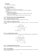
Page 32: ...e depending on the air conditioner settings and the operation environment The final shifted value will be used as internal setting temperature and it is updated continuously whenever the electrical power is supplied to the unit 12 1 2 Cooling Operation 12 1 2 1 Thermostat control Compressor is OFF when Intake Air Temperature Internal Setting Temperature 1 5 C Compressor is ON after waiting for 3 m...

Page 33: ...an motor with speed of Lo is running for 30 seconds to detect the indoor intake air temperature Every 10 minutes the indoor temperature is judged For the 1st judgment If indoor intake temperature remote control setting temperature 2 C COOL mode is decided If 2 C indoor intake temperature remote control setting temperature 2 C DRY mode is decided If indoor intake temperature remote control setting ...

Page 34: ...th one fan speed only It starts when compressor starts operation and it stops 30 seconds after compressor stops operation 12 2 Airflow Direction 1 There are two types of airflow vertical airflow directed by horizontal vane and horizontal airflow directed by vertical vanes 2 Control of airflow direction can be automatic angles of direction is determined by operation mode heat exchanger temperature ...

Page 35: ... airflow direction can be set using remote control the vane swings left and right within the angles as stated below It does not swing during fan motor stop For heating mode operation the angle of the vane depends on the indoor heat exchanger temperature as Figure 1 below 2 Manual horizontal airflow direction can be set using remote control the angles of the vane are as stated below and the positio...

Page 36: ... is pressed Quiet LED illuminates b Quiet operation stop condition 1 When one of the following conditions is satisfied quiet operation stops a Powerful button is pressed b Stop by OFF ON switch c Timer off activates d Quiet button is pressed again e Eco Patrol button is pressed f Mild Dry Cooling button is pressed 2 When quiet operation is stopped operation is shifted to normal operation with prev...

Page 37: ...h timer set will stop operate at set time 12 6 Auto Restart Control 1 When the power supply is cut off during the operation of air conditioner the compressor will re operate within three to four minutes there are 10 patterns between 2 minutes 58 seconds and 3 minutes 52 seconds to be selected randomly after power supply resumes 2 This type of control is not applicable during ON OFF Timer setting 1...

Page 38: ...ops condition when any of the following condition is fulfilled When OFF ON button is selected During any operation with Patrol PATROL e ion button is pressed When OFF Timer activates To disable the Patrol Operation during unit starts default with OFF ON button Press Set button continuously for 15 seconds by using pointer during Air Conditioner is OFF condition to enter internal setting mode Press ...

Page 39: ...erate for 30 seconds e ion Control e ion operation starts condition When dirtiness at level 2 2 minutes after stabilization time 4 hours at level 0 e ion operation time If dirtiness level improves from level 2 to level 1 the unit carries out level change after 60 seconds When dirtiness level returns to level 0 continuously for 11 minutes or more e ion operation stops Dirtiness Level and fan speed ...

Page 40: ...is selected e ion individual operation starts b e ion operation stop condition When OFF ON button is pressed to stop the operation When PATROL e ion button is pressed When OFF Timer activates c e ion operation pause condition When indoor fan stop during deice odor cut control thermostat off etc e ion operation resume after indoor fan restarts When indoor intake temperature 40 C e ion operation res...

Page 41: ...mer activates during any operation all operation stops and the latest e ion operation status is saved d Indicator When e ion operation starts e ion indicator ON e e ion Check Mode e ion abnormality check mode Purpose is to improve sensor serviceability when sensor is malfunction 1 Control starting condition When all of the conditions are formed Not in Patrol Demo mode e ion operation mode ON When ...

Page 42: ...eration OFF Timer activates Power supply reset iii e ion breakdown Judgement Method When hi feedback voltage at microcontroller supplied to filter during e ion stop due to PCB or filter s high voltage power supply damage Operations except e ion continue Both Timer indicator and e ion indicator blink Troubleshooting Method Press PATROL e ion button or OFF ON button to stop the operation Change main...

Page 43: ...Abnormal judgment start condition Start from ECO Patrol Sensor power ON and end after 30 seconds b Control content Judge ECO Patrol Sensor power level every 100ms c Abnormal Judgment condition When ECO Patrol Sensor has continues for 25 seconds Hi level 2 Circuit Abnormal Fix Output Lo a Abnormal judgment start condition After ECO Patrol Sensor unit power ON and after pressed 70 seconds b Control ...

Page 44: ...ide comfort and energy saving ECO Patrol Start condition Press ECO Patrol button to select ECO1 and ECO2 ECO Patrol Stop condition Press ECO Patrol button again OFF Timer activates Press OFF ON button to turn off the air conditioner Press AUTO OFF ON button to turn off the air conditioner Press POWERFUL QUIET button Press Mild Dry Cooling button ECO Patrol operation could ON when any of the follow...

Page 45: ...ot be operated at the same time ECO Patrol sensor initialized time is 70 seconds from power supplied to ECO Patrol sensor or 70 seconds from the operation start ECO 1 Cooling Soft Dry Operation ECO 2 Cooling Soft Dry Operation ECO 1 Heating Operation ECO 2 Heating Operation ...

Page 46: ...e conditions are formed Operation stops Timer Cancel button pressed When ECO Patrol sensor check mode signal is not received for more than 30 seconds 3 Control content During ECO Patrol mode ON when check signal is received if 1 or 2 is detected ECO Patrol LED start blinking ECO Patrol sensor operation stops but the unit operates as normal and ECO Patrol sensor abnormal code is memorized the 4 tim...

Page 47: ...l be applied 13 1 4 IPM Power transistor Prevention Control A Overheating Prevention Control 1 When the IPM temperature rises to 110 C compressor operation will stop immediately 2 Compressor operation restarts after three minutes the temperature decreases to 95 C 3 If this condition repeats continuously 4 times within 20 minutes timer LED will be blinking F96 is indicated B DC Peak Current Control...

Page 48: ...ction temperature indoor piping temperature is below 4 C During Heating operations Indoor piping temperature indoor suction is under 5 C b Control contents Compressor stops and restart after 3 minutes If the conditions above happen 2 times within 20 minutes the unit will Stop operation Timer LED blinks and F91 indicated 13 1 7 Low Frequency Protection Control 1 When the compressor operate at frequ...

Page 49: ...cordingly in this control Fan speed will be increased slowly if the unit is in quiet mode but no change in normal cooling mode 13 2 4 Dew Prevention Control 2 1 To prevent dew formation at indoor unit discharge area 2 This control starts if all conditions continue for 20 minutes Operated with Cooling or Soft Dry Mode Indoor intake temperature is between 25 C and 29 C Outdoor air temperature is les...

Page 50: ... Control For Heating Operation 13 3 1 Intake Air Temperature Control Compressor will operate at limited frequency if indoor intake air temperature is 30 C or above 13 3 2 Outdoor Air Temperature Control The maximum current value is regulated when the outdoor air temperature rises above 14 C in order to avoid compressor overloading 13 3 3 Overload Protection Control The compressor operating frequen...

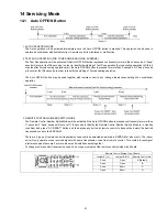
Page 51: ...control to set change the advance setting of air conditioner operation 3 REMOTE CONTROL NUMBER SWITCH MODE The Remote Control Number Switch Mode will be activated if the Auto OFF ON button is pressed continuously for more than 11 seconds 3 beep sounds will occur at 11th seconds to identify the Remote Control Number Switch Mode is in standby condition and press AC RESET button and then press any bu...

Page 52: ... SET button continuously for 10 seconds by using pointer Press TMER SET button until a beep sound is heard as confirmation of transmission code change To change the air quality sensor sensitivity Press and release by using pointer Press the Timer Decrement button to select sensitivity 1 Low Sensitivity 2 Standard Default 3 Hi Sensitivity Confirm setting by pressing Timer Set button a Beep sound wi...

Page 53: ... problems before inspecting the refrigeration cycle Such problems include insufficient insulation problem with the power source malfunction of a compressor and a fan The normal outlet air temperature and pressure of the refrigeration cycle depends on various conditions the standard values for them are shown in the table on the right ...

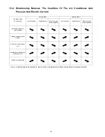
Page 54: ...es after an operation is started Cooling Mode Heating Mode Condition of the air conditoner Low Pressure High Pressure Electric current during operation Low Pressure High Pressure Electric current during operation Insufficient refrigerant gas leakage Clogged capillary tube or Strainer Short circuit in the indoor unit Heat radiation deficiency of the outdoor unit Inefficient compression ...

Page 55: ...unit is pressed To display memorized error Protective operation status 1 Turn power on 2 Press the CHECK button on the remote controller continuously for 5 seconds 3 will be displayed on the remote controller display Note Display only for No transmitting signal no receiving sound and no Power LED blinking 4 Press the TIMER or button on the remote controller The code H00 no abnormality will be disp...

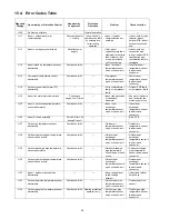
Page 56: ...r block H23 Indoor heat exchanger temperature sensor abnormality Continuous for 5s Indoor heat exchanger temperature sensor open or short circuit Indoor heat exchanger temperature sensor lead wire and connector H25 Indoor E Ion abnormality Port is ON for 10s during E Ion off E Ion PCB H27 Outdoor air temperature sensor abnormality Continuous for 5s Outdoor air temperature sensor open or short circ...

Page 57: ...r lock or feedback abnormal Outdoor fan motor lead wire and connector fan motor lock or block H98 Indoor high pressure protection Indoor high pressure protection Heating Check indoor heat exchanger air filter dirty air circulation short circuit H99 Indoor operating unit freeze protection Indoor freeze protection Cooling Check indoor heat exchanger air filter dirty air circulation short circuit F11...

Page 58: ... 3 times happen within 30 minutes Compressor overheat Insufficient refrigerant F98 Total running current protection 3 times happen within 20 minutes Total current protection Check refrigeration system power source or compressor lock F99 Outdoor direct current DC peak detection Continuous happen for 7 times Power transistor module current protection Power transistor module faulty or compressor lock...

Page 59: ...transmission is checked whether it is normal Malfunction Caused Faulty indoor unit PCB Faulty outdoor unit PCB Indoor unit outdoor unit signal transmission error due to wrong wiring Indoor unit outdoor unit signal transmission error due to breaking of wire in the connection wires between the indoor and outdoor units Indoor unit outdoor unit signal transmission error due to disturbed power supply w...

Page 60: ...are interconnected Malfunction Caused Wrong models interconnected Wrong indoor unit or outdoor unit PCBs mounted Indoor unit or outdoor unit PCBs defective Indoor outdoor unit signal transmission error due to wrong wiring Indoor outdoor unit signal transmission error due to breaking of wire 3 in the connection wires between the indoor and outdoor units Troubleshooting ...

Page 61: ...ction Decision Conditions During startup and operation of cooling and heating the temperatures detected by the indoor intake air temperature sensor are used to determine sensor errors Malfunction Caused Faulty connector connection Faulty sensor Faulty PCB Troubleshooting ...

Page 62: ...n Decision Conditions During startup and operation of cooling and heating the temperatures detected by the outdoor compressor temperature sensor are used to determine sensor errors Malfunction Caused Faulty connector connection Faulty sensor Faulty PCB Troubleshooting ...

Page 63: ...ions A current transformer CT is detected by checking the compressor running frequency rated frequency and CT detected input current less than 0 65A for continuously 20 seconds Malfunction Caused CT defective Outdoor PCB defective Compressor defective low compression Troubleshooting ...

Page 64: ...etermine abnormal fan motor feedback of rotation 2550rpm or 50rpm Malfunction Caused Operation stops due to short circuit inside the fan motor winding Operation stops due to breaking of wire inside the fan motor Operation stops due to breaking of fan motor lead wires Operation stops due to Hall IC malfunction Operation error due to faulty indoor unit PCB Troubleshooting ...

Page 65: ... Decision Conditions During startup and operation of cooling and heating the temperatures detected by the indoor heat exchanger temperature sensor are used to determine sensor errors Malfunction Caused Faulty connector connection Faulty sensor Faulty PCB Troubleshooting ...

Page 66: ...m Abnormal Malfunction Decision Conditions During standby of cooling and heating operation e ion breakdown occurs and air conditioner stops operation Malfunction Caused Faulty indoor main PCB Faulty indoor e ion power module Troubleshooting ...

Page 67: ...ction Decision Conditions During startup and operation of cooling and heating the temperatures detected by the outdoor air temperature sensor are used to determine sensor errors Malfunction Caused Faulty connector connection Faulty sensor Faulty PCB Troubleshooting ...

Page 68: ...ction Decision Conditions During startup and operation of cooling and heating the temperatures detected by the outdoor pipe temperature sensor are used to determine sensor errors Malfunction Caused Faulty connector connection Faulty sensor Faulty PCB Troubleshooting ...

Page 69: ...tion Decision Conditions During startup and operation of cooling and heating the temperatures detected by the outdoor discharge pipe temperature sensor are used to determine sensor errors Malfunction Caused Faulty connector connection Faulty sensor Faulty PCB Troubleshooting ...

Page 70: ...nction Decision Conditions During startup and operation of cooling and heating the temperatures detected by the outdoor heat exchanger temperature sensor are used to determine sensor errors Malfunction Caused Faulty connector connection Faulty sensor Faulty PCB Troubleshooting ...

Page 71: ...alfunction Decision Conditions The supply power is detected for its requirement by the indoor outdoor transmission Malfunction Caused Wrong models interconnected Wrong indoor unit and outdoor unit PCBs used Indoor unit or outdoor unit PCB defective Troubleshooting ...

Page 72: ...ction Decision Conditions During startup and operation of cooling and heating the temperatures detected by the outdoor heat sink temperature sensor are used to determine sensor errors Malfunction Caused Faulty connector connection Faulty sensor Faulty PCB Troubleshooting ...

Page 73: ...Decision Conditions During startup and operation of cooling and heating the temperatures detected by the outdoor gas pipe temperature sensor are used to determine sensor errors Malfunction Caused Faulty connector connection Faulty sensor Faulty PCB Troubleshooting ...

Page 74: ...ction Decision Conditions During startup and operation of cooling and heating the temperatures detected by the outdoor liquid pipe temperature sensor are used to determine sensor errors Malfunction Caused Faulty connector connection Faulty sensor Faulty PCB Troubleshooting ...

Page 75: ...lity Malfunction Decision Conditions If Patrol sensor feedback is 0V or 5V continuous for 6 hours Error will display only when the Patrol operation is ON Malfunction Caused Faulty connector connection Faulty Patrol sensor Troubleshooting ...

Page 76: ...eration is used to determine abnormal fan motor Malfunction Caused Operation stops due to short circuit inside the fan motor winding Operation stops due to breaking of wire inside the fan motor Operation stops due to breaking of fan motor lead wires Operation stops due to Hall IC malfunction Operation error due to faulty outdoor unit PCB Troubleshooting ...

Page 77: ...ture detected by the indoor pipe temperature sensor is above 60e C Malfunction Caused Air short circuit at indoor unit Clogged indoor unit air filter Dust accumulation on the indoor unit heat exchanger 2 3 way valve closed Faulty indoor unit fan motor Excessive refrigerant Clogged expansion valve or strainer Faulty indoor pipe temperature sensor Faulty indoor unit PCB Troubleshooting ...

Page 78: ... takes place when indoor pipe temperature is lower than 2e C Malfunction Caused Air short circuit at indoor unit Clogged indoor unit air filter Dust accumulation on the indoor unit heat exchanger 2 3 way valve closed Faulty indoor unit fan motor Refrigerant shortage refrigerant leakage Clogged expansion valve or strainer Faulty indoor pipe temperature sensor Faulty indoor unit PCB Troubleshooting ...

Page 79: ...onditions When heating operation when indoor pipe temperature is below 10 C When cooling operation when indoor pipe temperature is above 45 C Malfunction Caused Connector in poor contact Faulty sensor Faulty outdoor unit PCB 4 way valve defective Troubleshooting ...

Page 80: ...rature and indoor pipe temperature is above 10 C or indoor pipe temperature is below 1 0 C Remark When the indoor standby unit is freezing the outdoor unit transfers F17 error code to the corresponding indoor unit and H39 to other indoor unit s Malfunction Caused Wrong wiring connection Faulty sensor Faulty expansion valve Troubleshooting ...

Page 81: ...peration of cooling and heating when Power Factor Correction PFC protection circuitry at the outdoor unit main PCB senses abnormal high DC voltage level Malfunction Caused DC voltage peak due to power supply surge DC voltage peak due to compressor windings not uniform Faulty outdoor PCB Troubleshooting ...

Page 82: ...cking the CT detected input current value and the compressor running frequency During startup and operating of cooling and heating input current 8 78 256 A Hz x compressor running frequency 0 25 Gas shortage detection 2 A gas shortage is detected by checking the difference between indoor pipe temperature and indoor intake air temperature during cooling and heating Malfunction Caused Faulty indoor ...

Page 83: ...ion Decision Conditions A compressor rotation failure is detected by checking the compressor running condition through the position detection circuit Malfunction Caused Compressor terminal disconnect Faulty Outdoor PCB Faulty compressor Troubleshooting ...

Page 84: ...re data 61e C is detected by the outdoor pipe temperature sensor Malfunction Caused Air short circuit at outdoor unit Dust accumulation on the outdoor unit heat exchanger 2 3 way valve closed Faulty outdoor unit fan motor Excessive refrigerant Clogged expansion valve or strainer Faulty outdoor pipe temperature sensor Faulty outdoor unit PCB Troubleshooting ...

Page 85: ...vated Heat Sink Overheating During operation of cooling and heating when heat sink temperature data 90 C is detected by the heat sink temperature sensor Malfunction Caused IPM overheats due to short circuit of hot discharge air flow IPM overheats due to defective of outdoor fan motor IPM overheats due to defective of internal circuitry of IPM IPM overheats due to defective IPM temperature sensor M...

Page 86: ...ing and heating when compressor tank temperature data 112e C is detected by the compressor tank temperature sensor Malfunction Caused Faulty compressor tank temperature sensor 2 3 way valve closed Refrigerant shortage refrigerant leakage Faulty outdoor unit PCB Faulty compressor Troubleshooting ...

Page 87: ...on of cooling and heating when an input over current X value in Total Running Current Control is detected by checking the input current value being detected by current transforme r CT with the compressor running Malfunction Caused Excessive refrigerant Faulty outdoor unit PCB Troubleshooting ...

Page 88: ...ng the power transistor Never touch any live parts for at least 10 minutes after turning off the circuit breaker If unavoidable necessary to touch a live part make sure the power transistor s supply voltage is below 50V using the tester For the UVW make measurement at the Faston terminal on the board of the relay connector Tester s negative terminal Power transistor UVW Power transistor UVW Tester...

Page 89: ...or Removal Procedures 16 1 1 To remove front grille 16 1 2 To remove horizontal vane WARNING High Voltage are generated in the electrical parts area by the capacitor Ensure that the capacitor has discharged sufficiently before proceeding with repair work Failure to heed this caution may result in electric shocks ...

Page 90: ...90 16 1 3 To remove power electronic controller ...

Page 91: ...91 16 1 4 To remove discharge grille 16 1 5 To remove control board ...

Page 92: ...92 16 1 6 To remove cross flow fan and indoor fan motor ...

Page 93: ...93 ...

Page 94: ... Panel Fig 1 2 Remove the 8 screws of the Front Panel Fig 2 3 Remove the Top Cover of the Electronic Controller Fig 3 4 Remove the Control Board Fig 4 5 Remove the 6 screws of the Electronic Controller Fig 5 Caution When handling electronic controller be careful of electrostatic discharge ...

Page 95: ...ration Characteristics 17 1 1 CS E24LKES CU E24LKE Cooling Characteristic at Different Outdoor Air Temperature Condition Indoor room temperature 27 19 C Remote control setting HI FAN COOL 16 C Compressor frequency Fc Voltage 230 V ...

Page 96: ...96 Cooling Characteristic at Different Piping Length Condition Indoor room temperature 27 19 C 35 C Remote control setting HI FAN COOL 16 C Compressor frequency Fc Voltage 230 V ...

Page 97: ...97 Heating Characteristic at Different Outdoor Air Temperature Condition Indoor room temperature 20 C Remote control setting HI FAN HEAT 30 C Compressor frequency Fh Voltage 230 V ...

Page 98: ...98 Heating Characteristic at Different Piping Length Condition Indoor room temperature 20 C 7 6 C Remote control setting HI FAN HEAT 30 C Compressor frequency Fh Voltage 230 V ...

Page 99: ...7 1 2 CS E28LKES CU E28LKE Cooling Characteristic at Different Outdoor Air Temperature Condition Indoor room temperature 27 19 C Remote control setting HI FAN COOL 16 C Compressor frequency Fc Voltage 230 V ...

Page 100: ...100 Cooling Characteristic at Different Piping Length Condition Indoor room temperature 27 19 C 35 C Remote control setting HI FAN COOL 16 C Compressor frequency Fc Voltage 230 V ...

Page 101: ...101 Heating Characteristic at Different Outdoor Air Temperature Condition Indoor room temperature 20 C Remote control setting HI FAN HEAT 30 C Compressor frequency Fh Voltage 230 V ...

Page 102: ...102 Heating Characteristic at Different Piping Length Condition Indoor room temperature 20 C 7 6 C Remote control setting HI FAN HEAT 30 C Compressor frequency Fh Voltage 230 V ...

Page 103: ... 5 85 4 71 2 45 22 0 C 8 07 5 55 2 01 7 54 5 34 2 17 7 02 5 15 2 32 6 38 4 91 2 50 Outdoor Temp C Indoor wet bulb temp 30 35 40 46 TC SHC IP TC SHC IP TC SHC IP TC SHC IP 17 0 C 7 59 5 75 2 33 7 09 5 52 2 50 6 59 5 30 2 68 6 00 5 04 2 89 19 0 C 7 65 2 54 19 5 C 8 33 6 02 2 37 7 79 5 79 2 55 7 24 5 57 2 73 6 59 5 30 2 94 22 0 C 9 08 6 25 2 41 8 48 6 01 2 60 7 89 5 79 2 78 7 18 5 53 2 99 TC Total Co...

Page 104: ...8 Exploded View and Replacement Parts List 18 1 Indoor Unit Note The above exploded view is for the purpose of parts disassembly and replacement The non numbered parts are not kept as standard service parts ...

Page 105: ...OVER 1 CWH13C1183 23 DISCHARGE GRILLE COMPLETE 1 CWE20C3007 24 FULCRUM 2 CWH621103 25 VERTICAL VANE 15 CWE241289 26 CONNECTING BAR 1 CWE261156 27 CONNECTING BAR 1 CWE261158 28 CONNECTING BAR 1 CWE261157 29 CONNECTING BAR 1 CWE261159 30 CONNECTING BAR 1 CWE261160 31 AIR SWING MOTOR 1 CWA98K1014 O 32 AIR SWING MOTOR 1 CWA981241 O 34 CAP DRAIN TRAY 1 CWH521096 35 HORIZONTAL VANE 1 CWE24C1295 36 BACK ...

Page 106: ...RONIC CONTROLLER ECO PATROL 1 CWA745791 O 58 COVER FOR PCB ECO UPPER 1 CWD933192 O 59 COVER FOR PCB ECO BOTTOM 1 CWD933193 O 60 LEAD WIRE PCB ECO 1 CWA67C8484 O 61 SENSOR COMPLETE ECO 1 CWA50C2709 O 62 COVER FOR RECEIVER UPPER 1 CWD933022 O 63 COVER FOR RECEIVER BOTTOM 1 CWD933209 O 64 OPERATING INSTRUCTION 1 CWF567267 65 INSTALLATION INSTRUCTION 1 CWF614211 REF NO PART NAME DESCRIPTION QTY CS E24...

Page 107: ...107 18 2 Outdoor Unit 18 2 1 CU E24LKE ...

Page 108: ...108 18 2 2 CU E28LKE Note The above exploded view is for the purpose of parts disassembly and replacement The non numbered parts are not kept as standard service parts ...

Page 109: ... Y A W 2 6 2 O 7 9 1 1 5 1 H W C 1 D R A O B F O O R P D N U O S 7 2 A 9 3 0 1 7 1 H W C 1 R E V O C L A N I M R E T 8 2 J 0 0 3 0 8 0 7 H W C 1 R E V O C L A N I M R E T T U N 9 2 5 8 1 2 C 0 5 A W C 1 P O T P M O C E T E L P M O C R O S N E S 0 3 0 1 0 1 1 7 H W C 1 R O S N E S R E D L O H 1 3 J 9 6 1 2 C 3 4 A W C 1 E T E L P M O C L I O C V 2 3 8 5 2 2 C 3 4 A W C 1 E V L A V P X E R O F E T E...

Reviews: