44
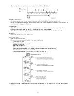
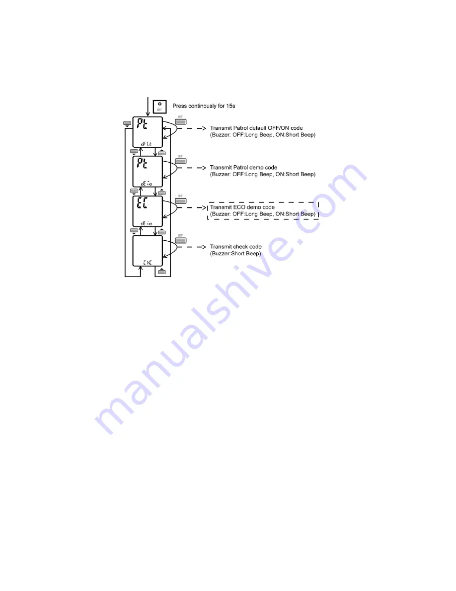
• ECO Patrol Demo Mode
- Press “Set” button continuously for 15 seconds by using pointer during Air Conditioner is OFF condition to enter internal
setting mode.
- Press “Timer Decrement” button to select “EC demo”.
- Press “Timer Set” button to toggle ECO Patrol Demo mode.
- Short “beep”: Turn ON ECO Patrol Demo mode.
- Long “beep”: Turn OFF ECO Patrol Demo mode.
Control details:
• During ECO Patrol Demo mode, operation LED ON and horizontal vane will set to Auto Swing.
• When Hi activity judge, Fan speed change to Hi Fan and ECO Patrol LED ON.
• When Lo activity judge, Fan speed change to Lo Fan and ECO Patrol LED OFF.
• No setting temperature adjustment.
• During ECO Patrol operation, the internal setting temperature and fan speed are adjusted in order to provide comfort and energy
saving.
• ECO Patrol Start condition.
- Press ECO Patrol button to select ECO1 and ECO2.
• ECO Patrol Stop condition.
- Press ECO Patrol button again.
- OFF Timer activates.
- Press OFF/ON button to turn off the air conditioner.
- Press AUTO OFF/ON button to turn off the air conditioner.
- Press POWERFUL/QUIET button.
- Press Mild Dry Cooling button.
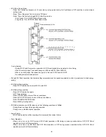
• ECO Patrol operation could ON when any of the following conditions is fulfilled:
- During forced cooling or forced heating operation.
- During e-ion or individual patrol operation.
• Power Failure
- ECO Patrol operation will be resuming after recovered from power failure.
• Timer Operation
- When unit is turn on by ON Timer and ECO Patrol operation is ON during previous operation before OFF, ECO Patrol
operation will not be ON automatically.
- When unit is turn on by ON Timer and ECO Patrol operation is OFF during previous operation before OFF, ECO Patrol
operation will not be ON automatically.
Summary of Contents for CS-E24LKES
Page 9: ...9 4 Location of Controls and Components 4 1 Indoor Unit 4 2 Outdoor Unit 4 3 Remote Control ...
Page 10: ...10 5 Dimensions 5 1 Indoor Unit Remote Control ...
Page 11: ...11 5 2 Outdoor Unit ...
Page 12: ...12 6 Refrigeration Cycle Diagram ...
Page 13: ...13 7 Block Diagram ...
Page 14: ...14 8 Wiring Connection Diagram 8 1 Indoor Unit ...
Page 15: ...15 8 2 Outdoor Unit 8 2 1 CU E24LKE ...
Page 16: ...16 8 2 2 CU E28LKE ...
Page 17: ...17 9 Electronic Circuit Diagram 9 1 Indoor Unit ...
Page 18: ...18 9 2 Outdoor Unit 9 2 1 CU E24LKE ...
Page 19: ...19 9 2 2 CU E28LKE ...
Page 20: ...20 10 Printed Circuit Board 10 1 Indoor Unit 10 1 1 Main Printed Circuit Board ...
Page 23: ...23 10 2 Outdoor Unit 10 2 1 Main Printed Circuit Board ...
Page 24: ...24 10 2 2 Power Printed Circuit Board ...
Page 90: ...90 16 1 3 To remove power electronic controller ...
Page 91: ...91 16 1 4 To remove discharge grille 16 1 5 To remove control board ...
Page 92: ...92 16 1 6 To remove cross flow fan and indoor fan motor ...
Page 93: ...93 ...


