24
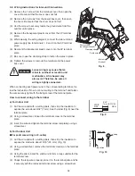
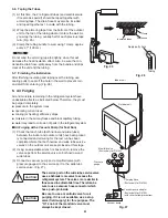
(4) With the “Lo” knob of the manifold valve open, run
the vacuum pump. The operation time for the vacu-
um pump varies with tubing length and the capacity
of the pump. The following table shows the amount
of time for evacuation:
Table 6
Required time for evacuation when
26.4 gal/h (100 liter/h) vacuum pump is used
If tubing length is
If tubing length is
less than 33 ft. (10 m)
more than 33 ft. (10 m)
10 min. or more
15 min. or more
The required time in Table 6 is calculated based on the
assumption that the ideal (or target) vacuum condition
is around 0.193 psi (10 mmHg abs.).
NOTE
To prevent other refrigerants from being mistakenly
charged to units which use R410A, the size of the
charge port on the service valve is different from the
one for other refrigerant types. For servicing such as
recharging, the specified charging hose, manifold and
vacuum pump adapter (with reverse flow prevention)
for R410A must be used.
NOTE
Be sure to completely insert the hex
wrench before attempting to turn the valve.
This may cause the refrigerant gas to
leak. In order to avoid this, take off the
hose quickly.
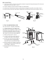
(5) With the vacuum pump still running, close the “Lo”
knob of the manifold valve. Then stop the vacuum
pump.
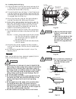
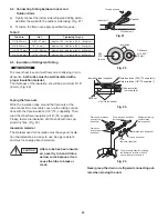
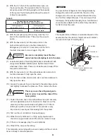
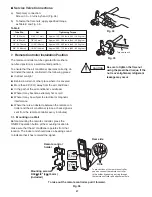
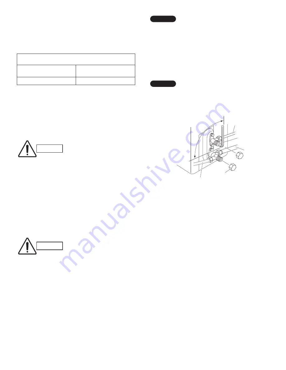
(6) With the hex wrench, turn the valve stem on the
narrow tube service valve counter-clockwise by
90 degrees (1/4 turn) for 10 seconds, and then turn
the stem clockwise to close it again. (Fig. 28)
(7) Leak test all joints at the tubing (both indoor and outdoors) with
soapy water. Bubbles indicate a leak. Tighten the joint more
when leaks, then check if there is no leak. Be sure to wipe off the
soap with a clean cloth.
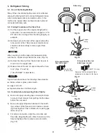
(8) With the hex wrench, turn the wide tube service valve stem
counter-clockwise to fully open the valve.
(9) Turn the narrow tube service valve stem counter-clockwise to
fully open the valve.
(10) Loosen the vacuum hose connected to the wide tube service
port slightly to release the pressure. Then, remove the hose.
(11) Fasten the valve cap on the wide tube service port securely
with an adjustable wrench or box wrench. Next, mount the
valve cap on the service valve and tighten it to 170 lbs·in
(200 kgf·cm) with a torque wrench. This process is very
important to prevent gas from leaking from the system.
(12) Test run the air conditioner. (See next page.)
(13) While the air conditioner is running, apply liquid soap to
check for any gas leaks around the service valves or caps.
(14) If there is no leakage, stop the air conditioner.
(15) Wipe off the soap on the tubing.
This completes air purging with a vacuum pump and the air condi-
tioner is ready for actual operation.
CAUTION
CAUTION
90° (1/4 turn)
Narrow tube
Hex wrench
Wide tube
Valve cap
Vacuum hose to manifold valve
Fig. 28
Summary of Contents for CS-KS12NB41
Page 37: ...Outdoor Unit CU KS12NK1A 8FA2 5251 12300 2 37 ...
Page 69: ......
Page 117: ......
Page 118: ...Operating Instructions CZ RD515U 852 6 4181 230 00 1 APPENDIX C A 3 ...
Page 129: ......
Page 130: ...A 4 INSTALLATION INSTRUCTIONS CZ RD515U 852 6 4190 592 00 0 APPENDIX D ...
Page 135: ......
Page 136: ...DC1111 0 ...

