ACL
(Reset)
button
1HR.
TIMER
button
ON/OFF
operation
button
HIGH POWER
button
Test run mode
Self-diagnostic mode
Address setting mode
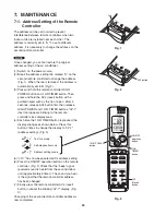
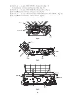
Fig. 1
Fig. 2
Fig. 3
Tab
ACL button
7. MAINTENANCE
7-1. Address Setting of the Remote
Controller
The address can be set in order to prevent
interference between remote controllers when two
indoor units are installed near each other. The
address is normally set to "A." To set a different
address, it is necessary to change the address on the
second remote controller.
Once changed, you cannot restore the original
address setting of the air conditioner.
(1) Switch on the power source.
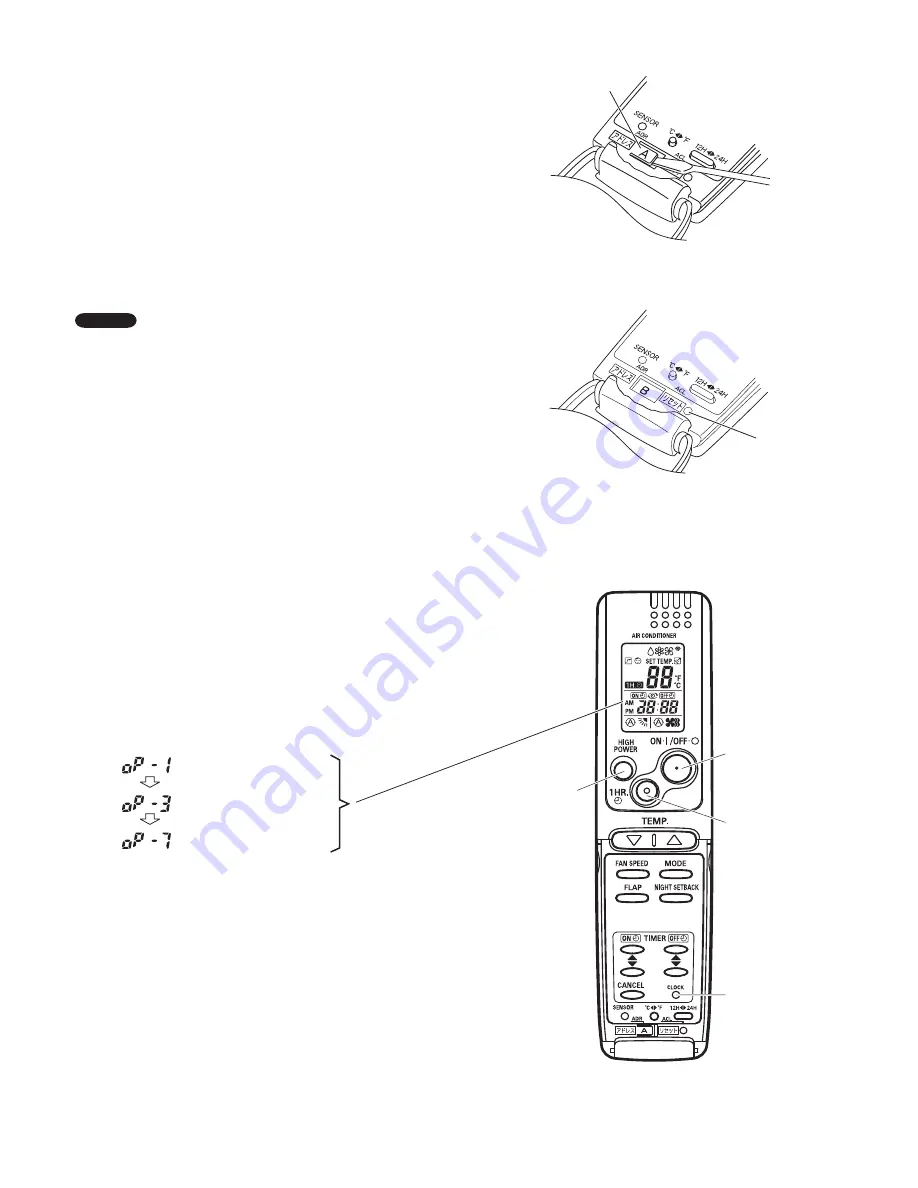
(2) Break the address-setting tab marked "A" on the
second remote controller to change the address
(Fig. 1). When the tab is removed, the address is
automatically set to B (Fig. 2).
(3) Press and hold the remote controller HIGH
POWER button and 1 HR TIMER button. Then,
press and hold the ACL (reset) button with a
pointed object such as the tip of a pen. After 5
seconds, release ACL button first, then release
HIGH POWER and 1 HR. TIMER buttons, "oP-1"
(test run) appears, blinking in the remote
controller clock display area.
(4) Each time the 1 HR TIMER button is pressed, the
display changes as shown below. Press this
button 2 times to change the display to "oP-7"
(address setting). (Fig. 3)
(5) "oP-7" has now been selected for address setting.
(6) Press the ON/OFF operation button on the remote
controller. (Fig. 3) Check that the "beep" signal
received sound is heard from the second indoor
unit (approximately 5 times). The sound you hear
is the signal that the remote controller address
has been changed.
(7) Finally press the remote controller ACL (reset)
button to cancel the blinking "oP-7" display. (Fig.
3)
Changing of the second remote controller address is
now completed.
NOTE
39
Summary of Contents for CS-KS12NB41
Page 37: ...Outdoor Unit CU KS12NK1A 8FA2 5251 12300 2 37 ...
Page 69: ......
Page 117: ......
Page 118: ...Operating Instructions CZ RD515U 852 6 4181 230 00 1 APPENDIX C A 3 ...
Page 129: ......
Page 130: ...A 4 INSTALLATION INSTRUCTIONS CZ RD515U 852 6 4190 592 00 0 APPENDIX D ...
Page 135: ......
Page 136: ...DC1111 0 ...

