1
2
3
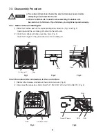
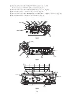
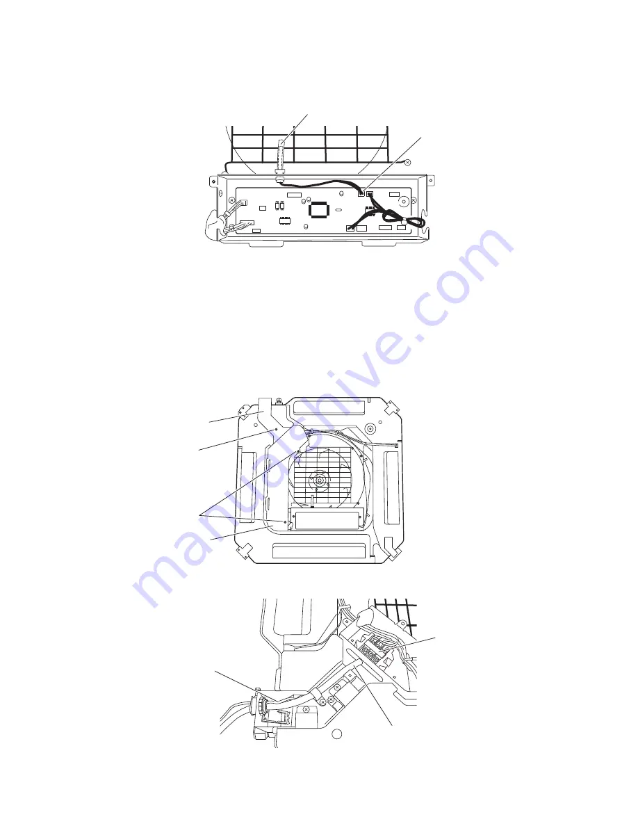
7-3-4. Remove the indoor air temperature sensor.
(1) Disconnect the connector CN08 (ROOM 2P) in the control box and remove the indoor air temperature
sensor. (Fig. 10)
7-3-5. Remove the power box and control box.
(1) Remove a screw and remove the terminal cover. (Fig. 11)
(2) Remove the 2 screws and remove the power box cover. (Fig. 11)
(3) Disconnect the power lines (No. 1 and No. 2) / signal line (No. 3) and ground cable from the terminals in
the power box. (Fig. 12)
Indoor air temperature sensor
CN08
Terminal
Fig.10
Fig.11
Fig.12
Ground cable
Terminal cover
Screw
Screw
Power box cover
Power lines / Signal line
43
Summary of Contents for CS-KS12NB41
Page 37: ...Outdoor Unit CU KS12NK1A 8FA2 5251 12300 2 37 ...
Page 69: ......
Page 117: ......
Page 118: ...Operating Instructions CZ RD515U 852 6 4181 230 00 1 APPENDIX C A 3 ...
Page 129: ......
Page 130: ...A 4 INSTALLATION INSTRUCTIONS CZ RD515U 852 6 4190 592 00 0 APPENDIX D ...
Page 135: ......
Page 136: ...DC1111 0 ...


