1
2
3
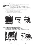
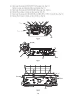
(4) Disconnect the connector CN07 (DP 2P) in the power box. (Fig. 13)
Remove a screw and disconnect the ground cable. (Fig. 13)
(5) Disconnect the connector CN03 (DCM 6P) in the power box. (Fig. 14)
(6) Remove the 4 screws and remove the power box. (Fig. 14)
(7) Disconnect the connectors CN06 (FS 3P) and CN09 (COIL-1 2P) in the control box. (Fig. 15)
(8) Remove the 2 screws and remove the control box. (Fig. 15)
Fig.13
Fig.14
Fig.15
Screw
Screw
Screw
Screw
Screw
CN06
CN03
Screw
Screw
Ground cable
CN07
CN09
44
Summary of Contents for CS-KS12NB41
Page 37: ...Outdoor Unit CU KS12NK1A 8FA2 5251 12300 2 37 ...
Page 69: ......
Page 117: ......
Page 118: ...Operating Instructions CZ RD515U 852 6 4181 230 00 1 APPENDIX C A 3 ...
Page 129: ......
Page 130: ...A 4 INSTALLATION INSTRUCTIONS CZ RD515U 852 6 4190 592 00 0 APPENDIX D ...
Page 135: ......
Page 136: ...DC1111 0 ...

