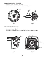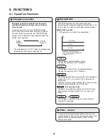
7-3-9. Remove the turbo fan and fan motor.
(1) Remove a nut and remove the turbo fan. (Fig. 22)
(2) Remove the 2 screws and 3 nuts, and remove the fan motor. (Fig. 23)
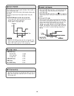
7-3-10. Remove the heat exchanger.
(1) Remove the 3 screws. (Fig. 24)
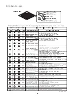
(2) Remove the 3 screws. (Fig. 25)
(3) Remove the heat exchanger from the main body upper section with the heat exchanger lifted.
Fig.22
Fig.23
Fig.24
Fig.25
Turbo fan
Nut
Screw
Nut
Fan motor
Screw
Screw
Heat exchanger
Screw
Main body
upper section
47
Summary of Contents for CS-KS12NB41
Page 37: ...Outdoor Unit CU KS12NK1A 8FA2 5251 12300 2 37 ...
Page 69: ......
Page 117: ......
Page 118: ...Operating Instructions CZ RD515U 852 6 4181 230 00 1 APPENDIX C A 3 ...
Page 129: ......
Page 130: ...A 4 INSTALLATION INSTRUCTIONS CZ RD515U 852 6 4190 592 00 0 APPENDIX D ...
Page 135: ......
Page 136: ...DC1111 0 ...

