83
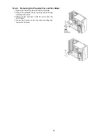
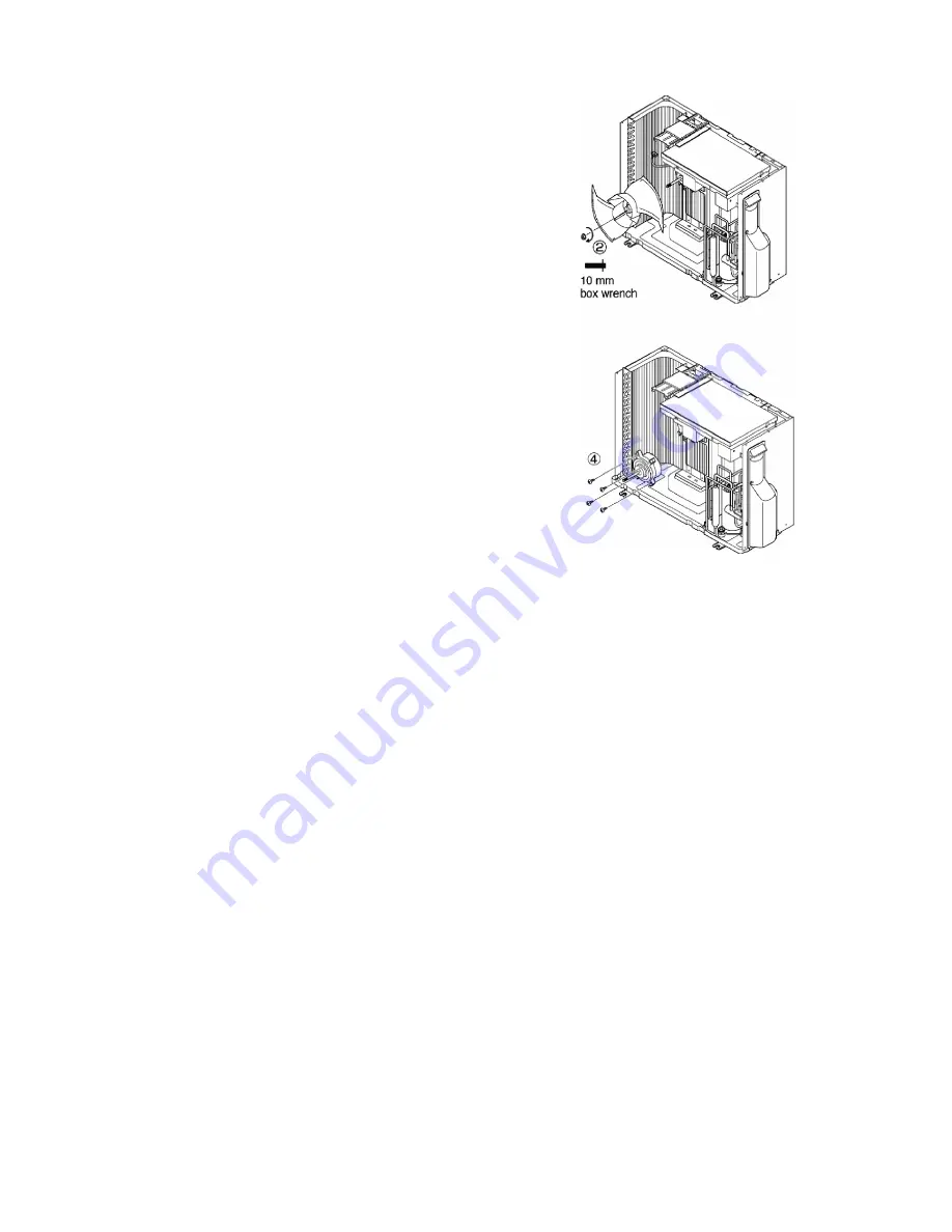
18.2.4. Removing the Propeller Fan and Fan Motor
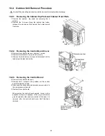
1. Remove the cabinet top plate and cabinet front plate.
2. Remove the propeller fan by removing the nut turning
clockwise at its center.
3. Disconnect the connector of the fan motor from the
control board.
4. Loosen the 4 screws at the fan motor mounting then
remove the fan motor.
Summary of Contents for CS-MRE12MKE
Page 15: ...15 4 Location of Controls and Components 4 1 Indoor Unit 4 2 Outdoor Unit 4 3 Remote Control ...
Page 16: ...16 5 Dimensions 5 1 Indoor Unit ...
Page 17: ...17 5 2 Outdoor Unit ...
Page 18: ...18 6 Refrigeration Cycle Diagram ...
Page 19: ...19 7 Block Diagram ...
Page 20: ...20 8 Wiring Connection Diagram 8 1 Indoor Unit ...
Page 21: ...21 8 2 Outdoor Unit ...
Page 22: ...22 9 Electronic Circuit Diagram 9 1 Indoor Unit ...
Page 23: ...23 9 2 Outdoor Unit ...
Page 24: ...24 10 Printed Circuit Board 10 1 Indoor Unit 10 1 1 Main Printed Circuit Board ...
Page 25: ...25 10 1 2 Power Printed Circuit Board 10 1 3 Indicator Printed Circuit Board ...
Page 26: ...26 10 2 Outdoor Unit ...
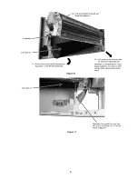
Page 79: ...79 18 1 3 To remove power electronic controller 18 1 4 To remove discharge grille ...
Page 80: ...80 18 1 5 To remove control board 18 1 6 To remove cross flow fan and indoor fan motor ...
Page 81: ...81 ...
Page 85: ...85 ...
Page 86: ...86 19 1 1 2 CS MRE9MKE ...
Page 87: ...87 ...
Page 88: ...88 19 1 2 Two Indoor Unit Operation 19 1 2 1 CS MRE7MKE x2 ...
Page 89: ...89 ...
Page 90: ...90 19 1 2 2 CS MRE9MKE CS MRE7MKE ...
Page 91: ...91 ...
Page 93: ...93 ...
Page 94: ...94 19 2 1 2 CS MRE9MKE ...
Page 95: ...95 ...
Page 96: ...96 19 2 1 3 CS MRE12MKE ...
Page 97: ...97 ...
Page 98: ...98 19 2 2 Two Indoor Unit Operation 19 2 2 1 CS MRE7MKE x2 ...
Page 99: ...99 ...
Page 100: ...100 19 2 2 2 CS MRE9MKE x2 ...
Page 101: ...101 ...
Page 102: ...102 19 2 2 3 CS MRE12MKE x2 ...
Page 103: ...103 ...

