11
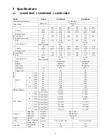
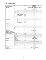
2.3.
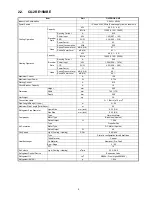
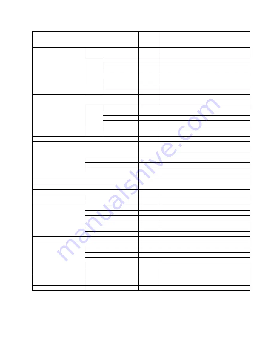
CU-2RE18MBE
Item
Unit
OUTDOOR UNIT
Indoor Unit Combination
3.2kW + 3.2kW
Power Source
1 Phase, 230V, 50Hz (Power supply from outdoor unit)
Cooling Operation
Capacity
kW
4.8 (1.5 ~ 5.0)
BTU/h
16400 (5120 ~ 17100)
Electrical
Data
Running Current
A
6.95
Power Input
kW
1.49 (0.27 ~ 1.58)
EER
W/W
3.22 (5.56 ~ 3.16)
Power Factor
%
93
Annual Consumption
kWh
745
Noise
Sound Pressure Level
dB-A (H/L)
49 / -
Sound Power Level
dB (H/L)
64 / -
Heating Operation
Capacity
kW
5.2 (1.1 ~ 6.7)
BTU/h
17700 (3750 ~ 22800)
Electrical
Data
Running Current
A
5.75
Power Input
kW
1.30k (0.24 ~ 1.70k)
COP
W/W
4.00 (4.58 ~ 3.94)
Power Factor
%
98
Noise
Sound Pressure Level
dB-A (H/L)
51 / -
Sound Power Level
dB (H/L)
66 / -
Maximum Current
A
12.0
Maximum Input Power
W
2.73k
Starting Current
A
6.95
Circuit Breaker Capacity
A
16
Dimension
Height
mm
540
Width
mm 780
(+70)
Depth
mm 289
Net Weight
kg
38
Connection Cable
3 + 1 (Earth) ø1.5 mm
2
Pipe Length Range (1 room)
m
3 ~ 20
Maximum Pipe Length (Total Room)
m
30
Refrigerant Pipe Diameter
Liquid Side
mm (inch)
6.35 (1/4)
Gas Side
mm (inch)
9.52 (3/8)
Compressor
Type
Hermetic Motor
Motor Type
Brushless (4-poles)
Rated Output
W
1.50k
Air Circulation
Type
Propeller Fan
Motor Type
DC Motor (8-poles)
Rated Output
W
40
Fan Speed
High (Cooling / Heating)
RPM
890 / 890
Heat Exchanger
Type
Plate fin configuration forced draft type
Tube Material
Copper
Fin Material
Aluminum (Pre Coat)
Row / Stage
2 / 20
FPI
19
Air Volume
High (Cooling / Heating)
m
3
/min
33.3 / 28.5
Refrigerant Control Device
Expansion Valve
Refrigerant Oil
cm
3
RB68A / Freol Alpha68M (350)
Refrigerant (R410A)
g
1.45k
Summary of Contents for CS-MRE7MKE
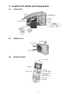
Page 15: ...15 4 Location of Controls and Components 4 1 Indoor Unit 4 2 Outdoor Unit 4 3 Remote Control ...
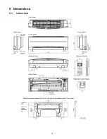
Page 16: ...16 5 Dimensions 5 1 Indoor Unit ...
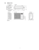
Page 17: ...17 5 2 Outdoor Unit ...
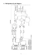
Page 18: ...18 6 Refrigeration Cycle Diagram ...
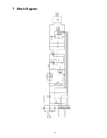
Page 19: ...19 7 Block Diagram ...
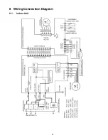
Page 20: ...20 8 Wiring Connection Diagram 8 1 Indoor Unit ...
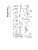
Page 21: ...21 8 2 Outdoor Unit ...
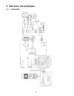
Page 22: ...22 9 Electronic Circuit Diagram 9 1 Indoor Unit ...
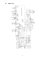
Page 23: ...23 9 2 Outdoor Unit ...
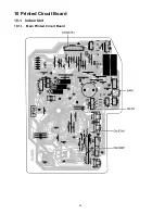
Page 24: ...24 10 Printed Circuit Board 10 1 Indoor Unit 10 1 1 Main Printed Circuit Board ...
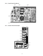
Page 25: ...25 10 1 2 Power Printed Circuit Board 10 1 3 Indicator Printed Circuit Board ...
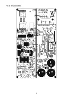
Page 26: ...26 10 2 Outdoor Unit ...
Page 79: ...79 18 1 3 To remove power electronic controller 18 1 4 To remove discharge grille ...
Page 80: ...80 18 1 5 To remove control board 18 1 6 To remove cross flow fan and indoor fan motor ...
Page 81: ...81 ...
Page 85: ...85 ...
Page 86: ...86 19 1 1 2 CS MRE9MKE ...
Page 87: ...87 ...
Page 88: ...88 19 1 2 Two Indoor Unit Operation 19 1 2 1 CS MRE7MKE x2 ...
Page 89: ...89 ...
Page 90: ...90 19 1 2 2 CS MRE9MKE CS MRE7MKE ...
Page 91: ...91 ...
Page 93: ...93 ...
Page 94: ...94 19 2 1 2 CS MRE9MKE ...
Page 95: ...95 ...
Page 96: ...96 19 2 1 3 CS MRE12MKE ...
Page 97: ...97 ...
Page 98: ...98 19 2 2 Two Indoor Unit Operation 19 2 2 1 CS MRE7MKE x2 ...
Page 99: ...99 ...
Page 100: ...100 19 2 2 2 CS MRE9MKE x2 ...
Page 101: ...101 ...
Page 102: ...102 19 2 2 3 CS MRE12MKE x2 ...
Page 103: ...103 ...


