63
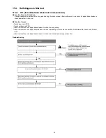
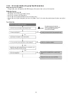
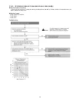
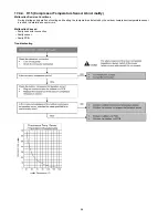
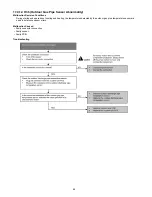
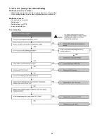
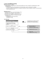
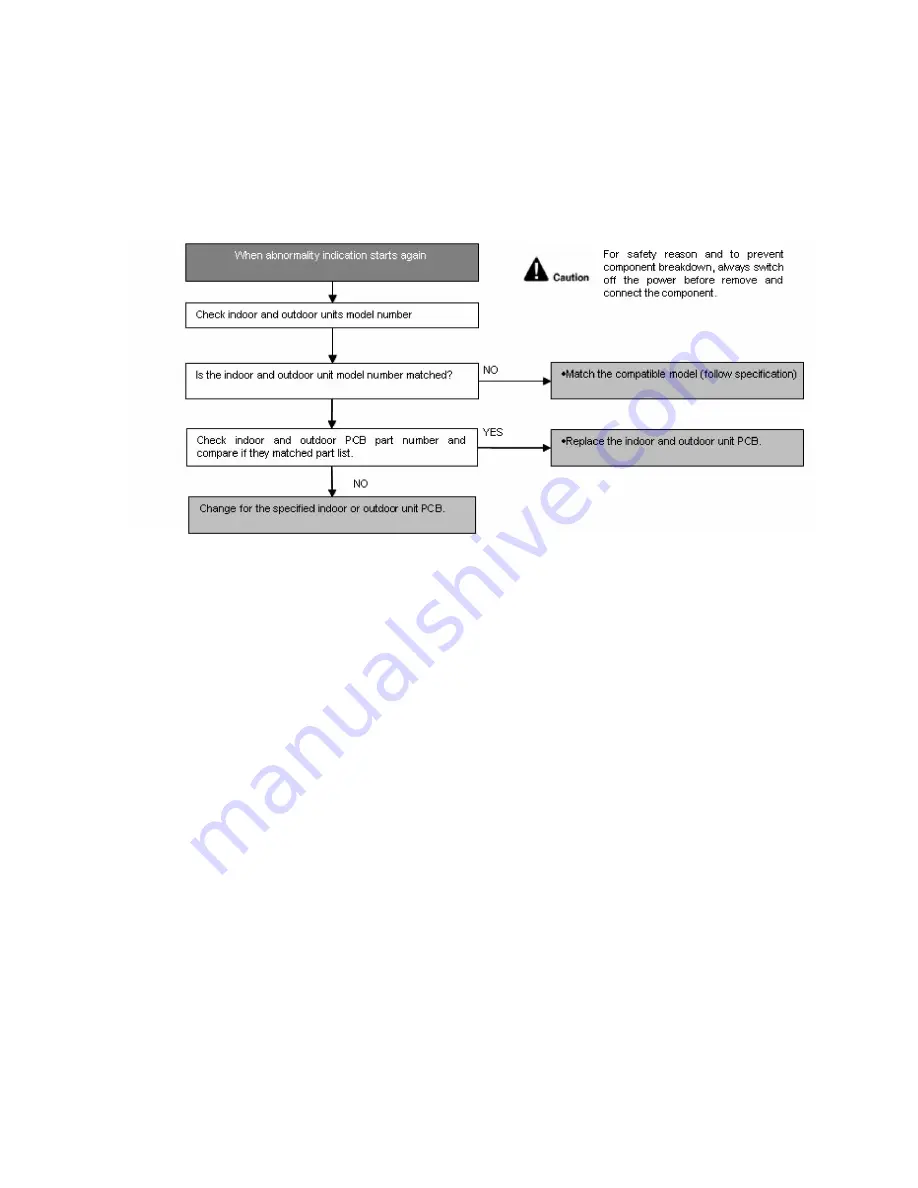
17.4.11. H33 (Unspecified Voltage between Indoor and Outdoor)
Malfunction Decision Conditions
The supply power is detected for its requirement by the indoor/outdoor transmission.
Malfunction Caused
• Wrong models interconnected.
• Wrong indoor unit and outdoor unit PCBs used.
• Indoor unit or outdoor unit PCB defective.
Troubleshooting
Summary of Contents for CS-MRE7MKE
Page 15: ...15 4 Location of Controls and Components 4 1 Indoor Unit 4 2 Outdoor Unit 4 3 Remote Control ...
Page 16: ...16 5 Dimensions 5 1 Indoor Unit ...
Page 17: ...17 5 2 Outdoor Unit ...
Page 18: ...18 6 Refrigeration Cycle Diagram ...
Page 19: ...19 7 Block Diagram ...
Page 20: ...20 8 Wiring Connection Diagram 8 1 Indoor Unit ...
Page 21: ...21 8 2 Outdoor Unit ...
Page 22: ...22 9 Electronic Circuit Diagram 9 1 Indoor Unit ...
Page 23: ...23 9 2 Outdoor Unit ...
Page 24: ...24 10 Printed Circuit Board 10 1 Indoor Unit 10 1 1 Main Printed Circuit Board ...
Page 25: ...25 10 1 2 Power Printed Circuit Board 10 1 3 Indicator Printed Circuit Board ...
Page 26: ...26 10 2 Outdoor Unit ...
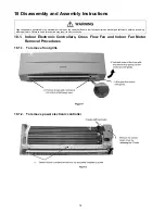
Page 79: ...79 18 1 3 To remove power electronic controller 18 1 4 To remove discharge grille ...
Page 80: ...80 18 1 5 To remove control board 18 1 6 To remove cross flow fan and indoor fan motor ...
Page 81: ...81 ...
Page 85: ...85 ...
Page 86: ...86 19 1 1 2 CS MRE9MKE ...
Page 87: ...87 ...
Page 88: ...88 19 1 2 Two Indoor Unit Operation 19 1 2 1 CS MRE7MKE x2 ...
Page 89: ...89 ...
Page 90: ...90 19 1 2 2 CS MRE9MKE CS MRE7MKE ...
Page 91: ...91 ...
Page 93: ...93 ...
Page 94: ...94 19 2 1 2 CS MRE9MKE ...
Page 95: ...95 ...
Page 96: ...96 19 2 1 3 CS MRE12MKE ...
Page 97: ...97 ...
Page 98: ...98 19 2 2 Two Indoor Unit Operation 19 2 2 1 CS MRE7MKE x2 ...
Page 99: ...99 ...
Page 100: ...100 19 2 2 2 CS MRE9MKE x2 ...
Page 101: ...101 ...
Page 102: ...102 19 2 2 3 CS MRE12MKE x2 ...
Page 103: ...103 ...

