50
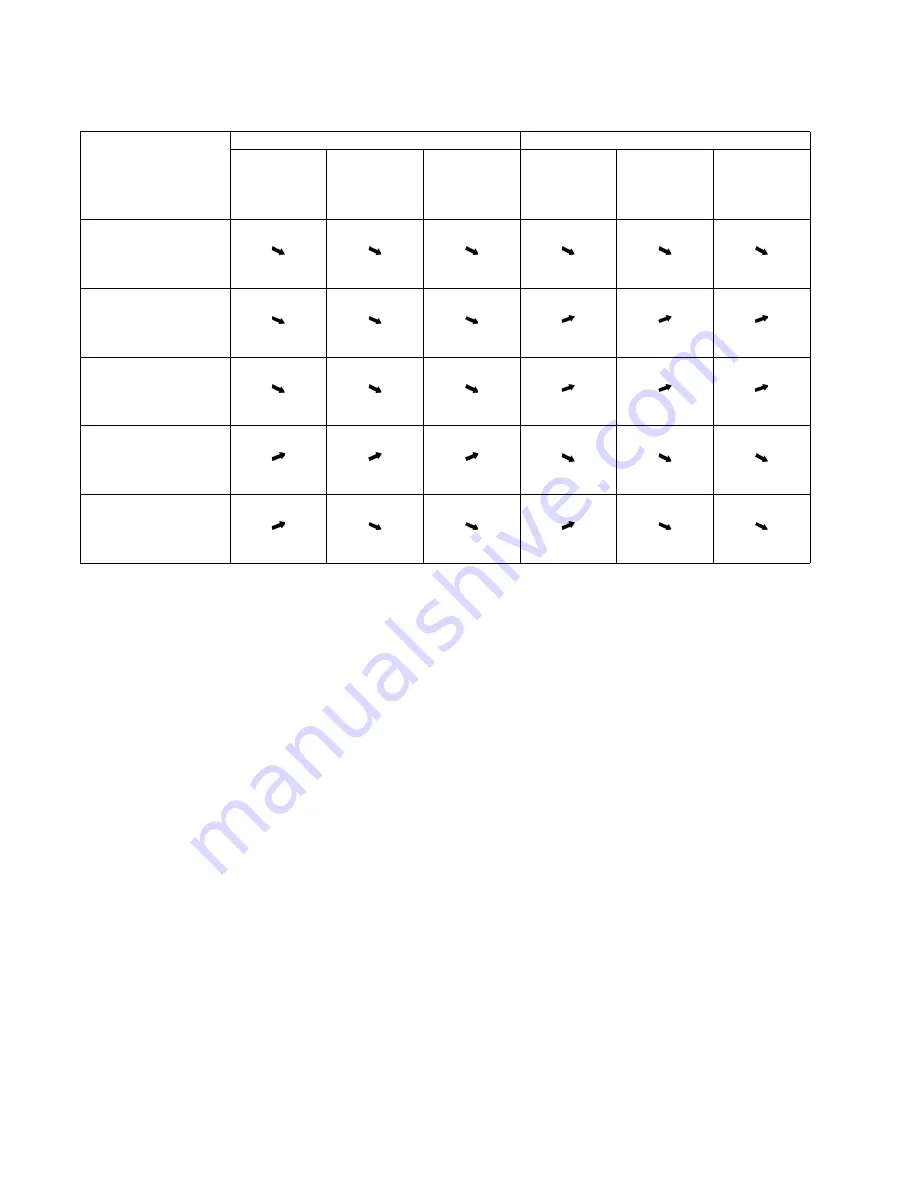
15.1.1. Relationship between the condition of the air conditioner and pressure and electric
current
• Carry out the measurements of pressure, electric current, and temperature fifteen minutes after an operation is started.
Cooling Mode
Heating Mode
Low Pressure
High Pressure
Electric current
during operating
Low Pressure
High Pressure
Electric current
during operating
Condition of the air
conditioner
Insufficient refrigerant
(gas leakage)
Clogged capillary tube
or Strainer
Short circuit in the
indoor unit
Heat radiation deficiency
of the outdoor unit
Inefficient compression
Summary of Contents for CS-NE9LKE
Page 12: ...12 4 Location of Controls and Components 4 1 Indoor Unit 4 2 Outdoor Unit 4 3 Remote Control...
Page 13: ...13 5 Dimensions 5 1 Indoor Unit...
Page 14: ...14 5 2 Outdoor Unit...
Page 15: ...15 6 Refrigeration Cycle Diagram...
Page 16: ...16 7 Block Diagram...
Page 17: ...17 8 Wiring Connection Diagram 8 1 Indoor Unit...
Page 18: ...18 8 2 Outdoor Unit...
Page 19: ...19 9 Electronic Circuit Diagram 9 1 Indoor Unit...
Page 20: ...20 9 2 Outdoor Unit...
Page 21: ...21 10 Printed Circuit Board 10 1 Indoor Unit 10 1 1 Main Printed Circuit Board...
Page 22: ...22 10 1 2 Power Printed Circuit Board 10 1 3 Indicator Printed Circuit Board...
Page 24: ...24 10 2 Outdoor Unit...
Page 80: ...80 16 1 3 To remove discharge grille...
Page 81: ...81 16 1 4 To remove control board 16 1 5 To remove cross flow fan and indoor fan motor...
Page 82: ...82...
Page 84: ...84 17 Technical Data 17 1 Operation Characteristics 17 1 1 CU NE9LKE...
Page 85: ...85...
Page 86: ...86...
Page 87: ...87...
Page 88: ...88 17 1 2 CU NE12LKE...
Page 89: ...89...
Page 90: ...90...
Page 91: ...91...


