21
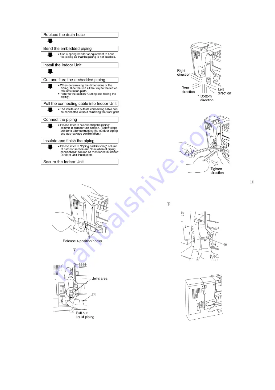
11.3.3.3. For the embedded piping
Install accessory of tube ass’y
1. Remove chassis back particular piece.
2. Connect tube ass’y to gas side piping. Liquid side
piping need to pull out to joint tube ass’y.
3. Set the piping direction.
(For bottom piping, need to perform cutting and flaring
process.)
4. Use 2 spanner to tighten the nut. (tighten torque 65 N
l
m)
5. Check gas leak at joint area using tube connector and
connect to liquid side piping. (Refer indication label at
chassis back for detail)
6. Cover the open tubing with the foam and bind it by
band
.
7. Close back the chassis back piece.
Summary of Contents for CS-PC36HKV
Page 9: ...9 5 Dimensions 5 1 Indoor Unit Remote Control 5 1 1 CS PC36HKV...
Page 10: ...10 5 2 Outdoor Unit 5 2 1 CU PC36HKV...
Page 11: ...11 6 Refrigeration Cycle Diagram...
Page 12: ...12 7 Block Diagram...
Page 13: ...13 8 Wiring Connection Diagram...
Page 14: ...14 9 Electronic Circuit Diagram 9 1 CS PC36HKV...
Page 15: ...15 9 2 CU PC36HKV...
Page 16: ...16 10 Printed Circuit Board 10 1 Indoor Unit...
Page 17: ...17 10 2 Outdoor Unit...
Page 18: ...18 10 3 Indicator...
Page 22: ...22 This can be used for left rear piping and left bottom piping also...
Page 45: ...45 17 Technical Data 17 1 Thermostat Characteristics Cooling Soft Dry...
Page 46: ...46 17 2 Operation Characteristics 17 2 1 CS PC36HKV CU PC36HKV...
Page 47: ...47...
Page 50: ...50 18 2 Outdoor Unit 18 2 1 CU PC36HKV...
Page 51: ...51...


