26
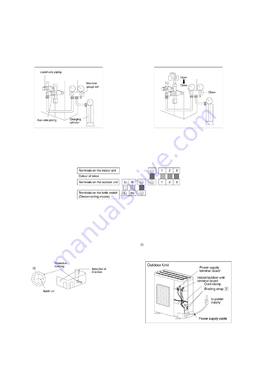
2) Air Purging
The air remaining in the Refrigeration cycle which contains moisture may cause malfunction on the Compressor.
1. To purge the air, push the pin on the Gas side 3-way valve for three seconds with a Hexagonal wrench and set it free for one
minute.
• Repeat this for three times.
2. To balance the refrigerant, close the low pressure side valve on the Manifold gauge and release refrigerant from the piping
through service port until the gauge indicates 0.5 -0.3MPa.
3. Set both 3-way valves to open position with the Hexagonal wrench for the unit operation.
11.4.4.
Connect The Cable To The Outdoor Unit
(FOR DETAIL REFER TO WIRING DIAGRAM AT UNIT)
1. Remove the control board cover from the unit by loosening the screw.
2. Connecting cable between indoor unit and outdoor unit shall be approved polychloroprene sheathed 4 x 1.5 mm
2
flexible
cord, type designation 245 IEC 57 or heavier cord.
3. Secure the cable onto the control board with the holder (clamper).
4. Cable connection to the power supply through knife switch (Disconnecting means).
• Connect the approved polychloroprene sheathed power supply cable (3 × 4.0 mm
2
), type designation 245 IEC 57 or heavier
cord to the terminal board, and connect the other end of the cable to knife switch (Disconnecting means).
5. Select required direction and apply protective bushing provided in accessories to protect cables from sharp edges.
6. Once all wiring work has been completed, tie the wires and cord stogether with the binding strap so that they do not touch
other parts such as the compressor and pipes.
7. For wire stripping and connection requirement, refer to instruction of indoor unit.
Note
: Knife switch (Disconnecting means) should have minimum 3.5 mm contact gap.
•
Secure the cable onto the control board with the holder (clamper).
Summary of Contents for CS-PC36HKV
Page 9: ...9 5 Dimensions 5 1 Indoor Unit Remote Control 5 1 1 CS PC36HKV...
Page 10: ...10 5 2 Outdoor Unit 5 2 1 CU PC36HKV...
Page 11: ...11 6 Refrigeration Cycle Diagram...
Page 12: ...12 7 Block Diagram...
Page 13: ...13 8 Wiring Connection Diagram...
Page 14: ...14 9 Electronic Circuit Diagram 9 1 CS PC36HKV...
Page 15: ...15 9 2 CU PC36HKV...
Page 16: ...16 10 Printed Circuit Board 10 1 Indoor Unit...
Page 17: ...17 10 2 Outdoor Unit...
Page 18: ...18 10 3 Indicator...
Page 22: ...22 This can be used for left rear piping and left bottom piping also...
Page 45: ...45 17 Technical Data 17 1 Thermostat Characteristics Cooling Soft Dry...
Page 46: ...46 17 2 Operation Characteristics 17 2 1 CS PC36HKV CU PC36HKV...
Page 47: ...47...
Page 50: ...50 18 2 Outdoor Unit 18 2 1 CU PC36HKV...
Page 51: ...51...


