41
16 Disassembly and Assembly Instructions
16.1. Indoor Electronic Controllers Removal Procedures
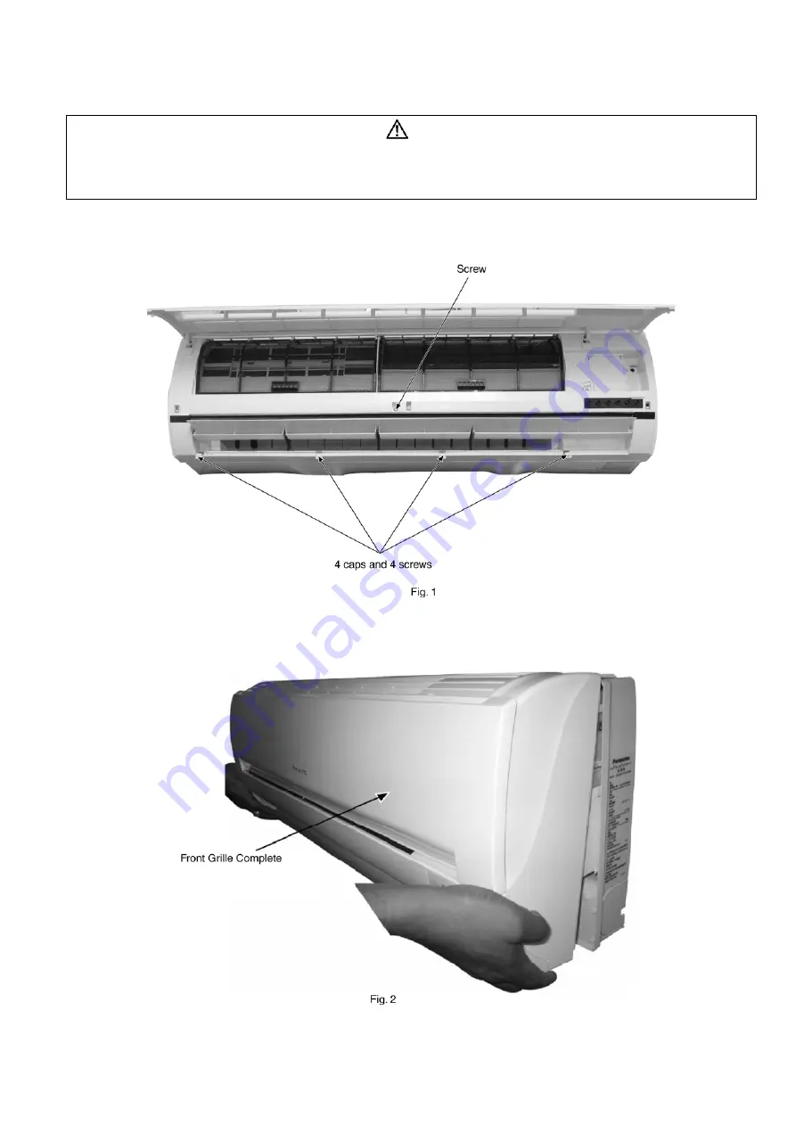
• Remove the screw at the middle of the Front Grille. (Fig. 1)
• Remove 4 caps and 5 screws at the bottom of the Front Grille. (Fig.1)
• Remove the Front Grille Complete. (Fig. 2)
WARNING
• Cautions! When handling electronic controller, be careful of electrostatic discharge.
• Be sure to return the wiring to its original position.
• There are many high voltage components within the heat sink cover so never touch the interior during operation. Wait at least two minutes after
power has been turned off.
Summary of Contents for CS-PC36HKV
Page 9: ...9 5 Dimensions 5 1 Indoor Unit Remote Control 5 1 1 CS PC36HKV...
Page 10: ...10 5 2 Outdoor Unit 5 2 1 CU PC36HKV...
Page 11: ...11 6 Refrigeration Cycle Diagram...
Page 12: ...12 7 Block Diagram...
Page 13: ...13 8 Wiring Connection Diagram...
Page 14: ...14 9 Electronic Circuit Diagram 9 1 CS PC36HKV...
Page 15: ...15 9 2 CU PC36HKV...
Page 16: ...16 10 Printed Circuit Board 10 1 Indoor Unit...
Page 17: ...17 10 2 Outdoor Unit...
Page 18: ...18 10 3 Indicator...
Page 22: ...22 This can be used for left rear piping and left bottom piping also...
Page 45: ...45 17 Technical Data 17 1 Thermostat Characteristics Cooling Soft Dry...
Page 46: ...46 17 2 Operation Characteristics 17 2 1 CS PC36HKV CU PC36HKV...
Page 47: ...47...
Page 50: ...50 18 2 Outdoor Unit 18 2 1 CU PC36HKV...
Page 51: ...51...


