background image

15

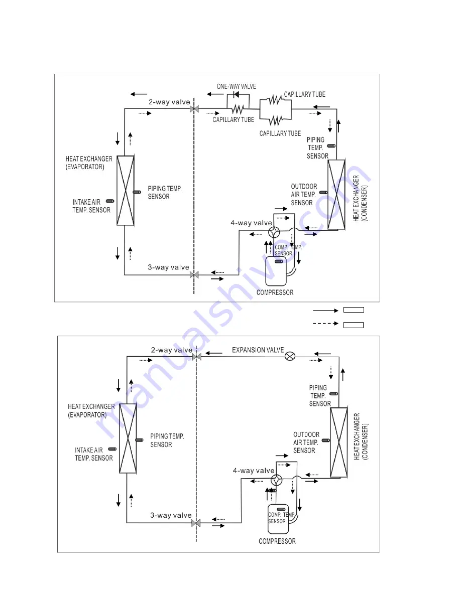
6. Refrigeration Cycle Diagram 

CS/CU-RE9JKE,  CS/CU- RE12JKE 

CS/CU-RE15JKE

COOLING 

HEATING 

Summary of Contents for CS-RE9JKE

Page 1: ...24 10 3 Outdoor Unit 26 11 Service Mode 29 11 1 Auto OFF ON Button 29 11 2 Select Remote Control Transmission Code29 11 3 Operate and Display of Remote Control 30 12 Operation Control 32 12 1 Basic Fu...

Page 2: ...g Guide 40 14 1 Refrigeration Cycle System 40 14 2 Break Down self Diagnosis Function 40 15 Disassembly and Assembly Instructions 43 16 Exploded View and Replacement Pars List 46 16 1 Indoor Unit 46 1...

Page 3: ...gly recommended to be installed with Earth Leakage Circuit Breaker ELCB or Residual Current Device RCD Otherwise it may cause electrical shock and fire in case equipment breakdown or insulation breakd...

Page 4: ...elect an installation location which is easy for maintenance 6 Power supply connection to the air conditioner Connect the power supply cord of the air conditioner to the mains using one of the followi...

Page 5: ...ch 6 35 1 4 Pipe Length m ft 3 9 8 15 49 2 Height Difference m ft 5 16 4 Additional Gas Amount g m oz ft 20 0 2 Refrigerant Charge Less m ft 7 5 24 6 Inner diameter mm 14 Drain Hose Length mm 500 Type...

Page 6: ...NG A 3 45 HEATING A 3 70 Maximum Current A 6 00 Power Factor COOLING 88 HEATING 96 Power factor means total figure of compressor indoor fan motor and outdoor fan motor Number of core 3 1 5mm Power Cor...

Page 7: ...5 1 4 Pipe Length m ft 3 9 8 15 49 2 Height Difference m ft 5 16 4 Additional Gas Amount g m oz ft 20 0 2 Refrigerant Charge Less m ft 7 5 24 6 Inner diameter mm 14 Drain Hose Length mm 500 Type Rotar...

Page 8: ...ING A 4 70 HEATING A 5 20 Maximum Current A 6 80 Power Factor COOLING 93 HEATING 93 Power factor means total figure of compressor indoor fan motor and outdoor fan motor Number of core 3 1 5mm Power Co...

Page 9: ...1 4 Pipe Length m ft 3 9 8 15 49 2 Height Difference m ft 5 16 4 Additional Gas Amount g m oz ft 20 0 2 Refrigerant Charge Less m ft 7 5 24 6 Inner diameter mm 14 Drain Hose Length mm 500 Type Scroll...

Page 10: ...LING A 6 05 HEATING A 7 10 Maximum Current A 9 70 Power Factor COOLING 90 HEATING 94 Power factor means total figure of compressor indoor fan motor and outdoor fan motor Number of core 3 1 5mm Power C...

Page 11: ...Improvement o Random auto restart after power failure for safety restart operation o Gas leakage protection o Prevent compressor reverse cycle o Inner protector to protect compressor x Operation Impr...

Page 12: ...se z Press RESET button to restore the remote control s default setting POWER GREEN TIMER ORANGE QUIET GREEN INDICATOR POWERFUL RED OFF ON Operation mode Airflow direction adjustment Timer setting Tem...

Page 13: ...13 5 Dimensions 5 1 Indoor Unit 60 Unit mm 55 290 825 848 204 61 10 5 49 63 60 119 3 404 6 38 12 5 56 16 195 60 548 398 Air outlet Air intake...

Page 14: ...14 5 2 Outdoor Unit Unit mm...

Page 15: ...15 6 Refrigeration Cycle Diagram CS CU RE9JKE CS CU RE12JKE CS CU RE15JKE COOLING HEATING...

Page 16: ...16 7 Block Diagram CS CU RE15JKE CS CU RE9 12JKE...

Page 17: ...17 8 Wiring Diagram 6 8 5 6 8 5...

Page 18: ...18 6 8 5...

Page 19: ...19 9 Printed Circuit Board 9 1 Indoor Unit 9 1 1 Main Printed Circuit Board TOP VIEW...

Page 20: ...20 BOTTOM VIEW...

Page 21: ...21 9 1 2 Indicator receiver TOP VIEW BOTTOM VIEW...

Page 22: ...22 9 2 Outdoor Unit 9 2 1 CU RE9JKE CU RE12JKE TOP VIEW BOTTOM VIEW...

Page 23: ...diation from the condenser is not obstructed x There should not be any animal or plant which could be affected by hot air discharged x Keep the spaces indicated by arrows from wall ceiling fence or ot...

Page 24: ...m this line 1 Mount the installation plate on the wall with 5 screws or more If mounting the unit on the wall consider using anchor bolts Always mount the installation plate horizontally by aligning t...

Page 25: ...25 10 2 3 Indoor Unit Installation...

Page 26: ...mm 2 When installing at roof please consider strong wind and earthquake Please fasten the installation stand firmly with bolt or nails 10 3 2 Connecting the Piping 10 3 2 1 Connecting the piping to i...

Page 27: ...2 UNF 20 threads 2 Connect the center hose of the charging set to a vacuum pump with check valve or vacuum pump and vacuum pump adaptor 3 Turn on the power switch of the vacuum pump and make sure that...

Page 28: ...mper 4 Attach the control board cover back to the original position with the screw 5 For wiring stripping and connection requirement refer to instruction 10 2 4 of indoor unit 10 3 5 Pipe Insulation 1...

Page 29: ...switch is continuously pressed between 16 to 21 seconds either H14 error detection selection mode or remote controller s signal receiving sound can be cancelled or turned on 11 2 Select Remote Contro...

Page 30: ...e AIR SWING button 11 3 5 AIR SWING button To adjust vertical airflow directions by pressing AIR SWING button 5 options 11 3 6 QUIET POWERFULL button Press this button to switch among QUIET operation...

Page 31: ...nce If the OFF ON button on the remote control or the AUTO Switch on the indoor unit is pressed the timer setting will be cancelled If Auto Restart Control occurs timer setting will be cancelled Durin...

Page 32: ...point 12 1 3 Soft Dry Operation 12 1 3 1 Thermostat control The same as Cooling mode 12 1 4 Heating operation 12 1 4 1 Thermostat control Compressor is OFF when Intake Air Temperature Internal Settin...

Page 33: ...ck control is performed once every second During fan motor on if fan motor feedback 2550 rpm or 50 rpm continue for 10 seconds then fan motor error counter increases fan motor then stops and restarts...

Page 34: ...ontrol Once Quiet mode is active the unit will continuously operate in QUIET Mode until cancel the mode by pressing QUIET POWERFUL button on remote control 12 3 4 Powerful operation To cooling or heat...

Page 35: ...urs 12 3 7 Timer control Delay ON Timer ca be set using remote controller the unit with timer set will start operate earlier than the setting time This is to provide a comfortable environment when rea...

Page 36: ...y instructed for compressor operation will be decreased 2 If the running current does not exceed I1 A for 5 seconds the frequency instructed will be increased RE9JKE RE12JKE RE15JKE Operation mode I1...

Page 37: ...tection Control a Control start conditions For 5 minutes the compressor continuously operates and outdoor total current is between 0 65A and 1 65A During Cooling and Soft Dry operations Indoor suction...

Page 38: ...Cooling or Soft Dry Mode Indoor intake temperature is between 25 and 29 Outdoor air temperature is less than 30 This control stopped then receive air swing change signal from Remote Control 13 2 4 Ov...

Page 39: ...ent the cold airflow from blowing If the piping temperature rises to 19 and the indoor fan speed and airflow direction varies with the indoor piping temperature the hot start control is completed 13 3...

Page 40: ...oor temperature 35 C at cooling mode and 7 C at heating mode Compressor operates at rated frequency Different in the intake and outlet air temperatures Normal Value of electric current during operatio...

Page 41: ...be restarted using AUTO Switch on the indoor unit In forced operation the frequency for compressor and fan speed can not be changed and the signal receiving sound is different Normal Operation ON pep...

Page 42: ...42 14 2 3 Error Codes Table...

Page 43: ...proceeding with repair work Failure to heed this caution may result in electric shocks 1 Open the intake grille and pull it to the horizontal position 2 Pull up the intake grille until it falls off 1...

Page 44: ...ow Green and take out the sensor from the holder on evaporator Pull out the whole electronic controller Be sure to avoid cracking of the supporting hook 4 Remove the control board complete Loose the s...

Page 45: ...or on the left side and pull out the whole evaporator 2 Loose the fixing screw of the cross flow fan 3 After removing the bearing indoor fan can be taken out from the left side 4 Lift up the indoor fa...

Page 46: ...46 16 Exploded View and Replacement Pars List 16 1 Indoor Unit CS RE9JKE CS RE12JKE CS RE15JKE...

Page 47: ...862 CWA20C2894 17 MAIN PCB 1 CWA73C3612 CWA73C3613 CWA73C3614 18 SENSOR 1 CWA50C2596 CWA50C2596 CWA50C2596 19 INDICATOR HOLDER FRONT 1 CWD933087 CWD933087 CWD933087 21 INDICATOR PCB 1 CWA745415 CWA745...

Page 48: ...48 16 2 Outdoor Unit CU RE9JKE CU RE12JKE...

Page 49: ...0300J 7080300J 20 SOUND PROOF BOARD 1 CWH151187 CWH151187 21 SOUND PROOF MATERIAL 1 CWG302433 CWG302433 22 TUBE NOISE SUPPRESSOR 1 CWB121016 CWB121016 23 REACTOR 1 G0C193J00007 G0C193J00007 24 CONTROL...

Page 50: ...50 CU RE15JKE...

Page 51: ...D PROOF MATERIAL 1 CWG302303 22 TUBE NOISE SUPPRESSOR 1 CWB14011 23 REACTOR 1 G0C203J00004 24 CONTROL BOX COMPLETE 1 CWH14C6795 26 TERMINAL BOARD ASS Y 1 CWA28K1185 27 CONTROL BOARD CASING 1 CWH102243...

Reviews: