111
15.2.1.3
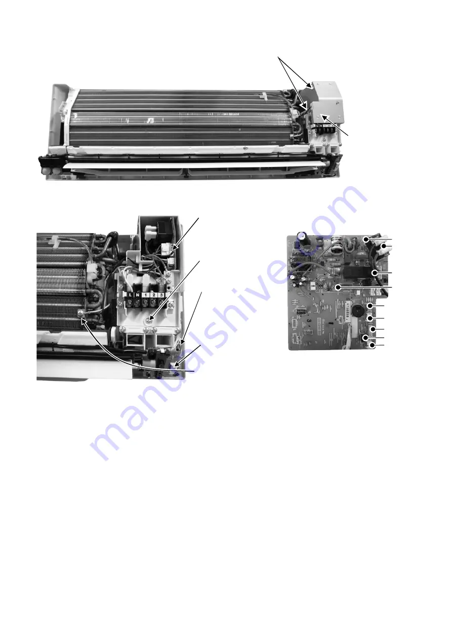
To remove power electronic controller
4.
Remove the control
board cover by
releasing the 2 hooks.
2 Hooks (left hand side)
Figure 13
6.
Detach the CN-DISP
connector then remove
the indicator complete.
7.
Detach the HV+ (White) &
HV- (Black) terminal
wires, CN1 and GND then
remove the high voltage
generator.
10. Detach 6 connectors as labeled from
the electronic controller. Then pull out
main controller gently
11. Detach AC303 (WHT), RY-PWR connector
(Black and Brown) from the electronic controller.
12. Detach AC304 (RED) from Terminal Board.
CN-STM2
CN-STM1
9. Pull out the main
electronic controller
controller halfway.
8.
Remove screw to
remove terminal board
complete.
5.
Detach the Earth wire
CN-MSENS
CN-TH
CN-CLN
CN-FM
AC303 (WHT)
RY-PWR
AC304 (RED)
Figure
14
Figure
15
Summary of Contents for CS-S9NKV
Page 15: ...15 4 2 3 CU S18NKV CU S24NKV...
Page 16: ...16 4 2 4 CU S28NKV...
Page 17: ...17 5 Refrigeration Cycle Diagram 5 1 CS S9NKV CU S9NKV CS S12NKV CU S12NKV...
Page 18: ...18 5 2 CS S18NKV CU S18NKV CS S24NKV CU S24NKV...
Page 19: ...19 5 3 CS S28NKV CU S28NKV...
Page 24: ...24 7 Wiring Connection Diagram 7 1 Indoor Unit 7 1 1 CS S9NKV CS S12NKV...
Page 25: ...25 7 1 2 CS S18NKV CS S24NKV...
Page 26: ...26 7 1 3 CS S28NKV...
Page 31: ...31 8 Electronic Circuit Diagram 8 1 Indoor Unit 8 1 1 CS S9NKV CS S12NKV...
Page 32: ...32 8 1 2 CS S18NKV CS S24NKV...
Page 33: ...33 8 1 3 CS S28NKV...
Page 41: ...41 9 1 5 Human Activity Sensor Printed Circuit Board...
Page 42: ...42 9 2 Outdoor Unit 9 2 1 Main Printed Circuit Board 9 2 1 1 CU S9NK...
Page 43: ...43 9 2 1 2 CU S12NK...
Page 44: ...44 9 2 1 3 CU S18NK CU S24NK...
Page 45: ...45 9 2 1 4 CU S28NK...
Page 46: ...46 9 2 2 Noise Filter Printed Circuit Board 9 2 2 1 CU S9NKV...
Page 47: ...47 9 2 2 2 CU S28NKV...


