12.5. Auto OFF/ON Button
•
The “Auto OFF/ON Button” (behind the front grille) is used to operate the air conditioner if remote control is misplaced or
mulfunctioning.
•
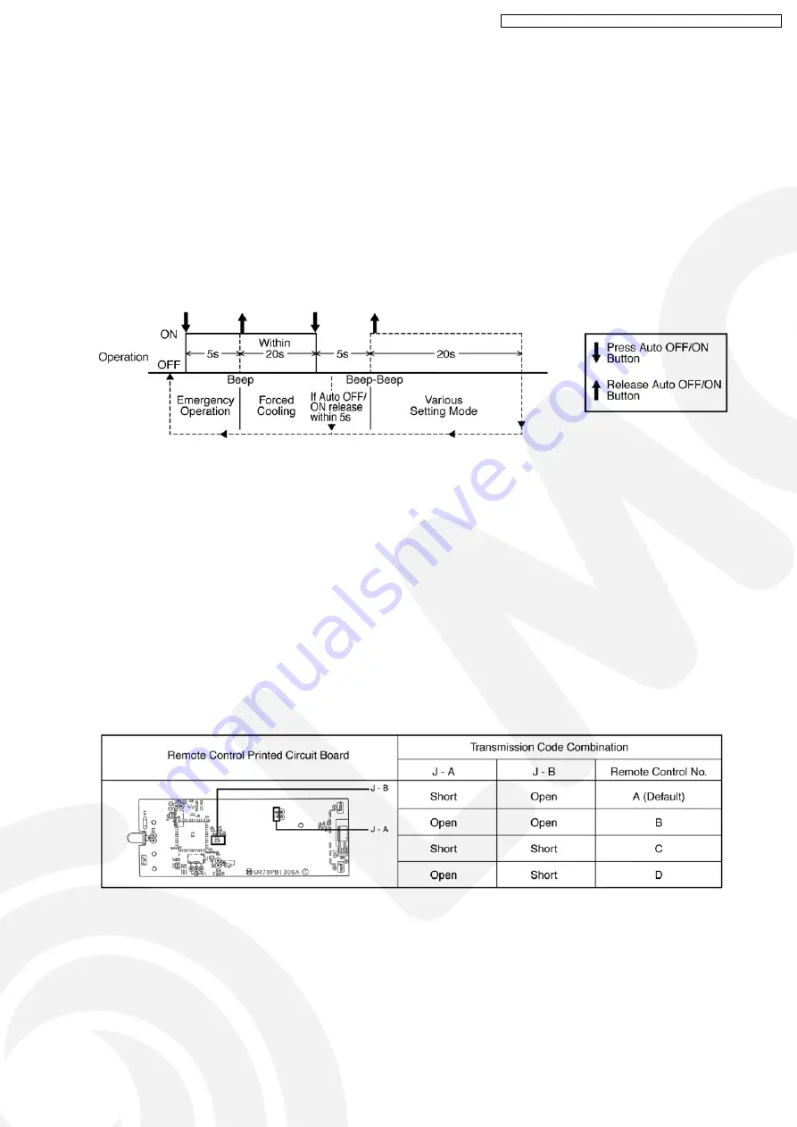
Forced cooling operation is possible by pressing the “Auto OFF/ON Button” for more than 5s where “beep” sound is heard then
release the button.
•
User able to select remote control transmission code and toggle remote control signal receiving sound under various setting
mode.
•
To enter various setting mode:
−
Press the “Auto OFF/ON Button” continuously for 5s (“beep” sound is heard) and release.
−
Within 20s, press the “Auto OFF/ON Button” continuously for 5s again (2 “beep” sound is heard) and release.
−
Various setting mode has limit up to 20s. Then return to normal operation.
12.5.1. Toggle Remote Control Signal Receiving Sound
•
Under various setting mode, press the “Auto OFF/ON Button” to toggle the remote control sound.
−
Short “beep”: Turn ON remote control signal receiving sound.
−
Long “beep”: Turn OFF remote control signal receiving sound.
•
After “Auto OFF/ON Button” is pressed, the 20s counter for various setting mode is restarted.
12.5.2. Select Remote Control Transmission Code
•
There are 4 types of remote control transmission code could be selected and stored in EEPROM of indoor unit. The indoor unit
will only operate when received signal with same transmission code from remote control. This could prevent signal interference
when there are 2 or more indoor unit installed nearby together.
•
To change remote control transmission code, short or open jumpers at the remote control printed circuit board.
•
Under various setting mode, after select the transmission code combination of remote control, press any button of remote
control to transmit a signal to indoor unit. The transmission code will be stored in EEPROM.
•
After signal is received, the various setting mode is cancelled and return to normal operation.
59
CS-V7DKE CU-V7DKE / CS-V9DKE CU-V9DKE / CS-V12DKE CU-V12DKE
Summary of Contents for CS-V7DKE
Page 15: ...5 Refrigeration Cycle Diagram 15 CS V7DKE CU V7DKE CS V9DKE CU V9DKE CS V12DKE CU V12DKE...
Page 16: ...6 Block Diagram 16 CS V7DKE CU V7DKE CS V9DKE CU V9DKE CS V12DKE CU V12DKE...
Page 17: ...7 Wiring Diagram 17 CS V7DKE CU V7DKE CS V9DKE CU V9DKE CS V12DKE CU V12DKE...
Page 64: ...14 3 3 CS V12DKE CU V12DKE 64 CS V7DKE CU V7DKE CS V9DKE CU V9DKE CS V12DKE CU V12DKE...
Page 75: ...75 CS V7DKE CU V7DKE CS V9DKE CU V9DKE CS V12DKE CU V12DKE...
Page 77: ...19 2 Remote Control 77 CS V7DKE CU V7DKE CS V9DKE CU V9DKE CS V12DKE CU V12DKE...
Page 79: ...TOP VIEW 79 CS V7DKE CU V7DKE CS V9DKE CU V9DKE CS V12DKE CU V12DKE...


