- 18 -
R
G
B
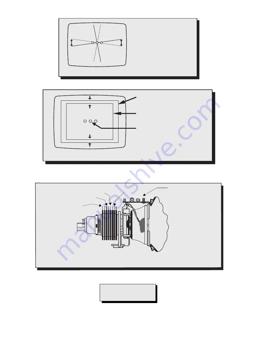
As the yoke is tilted
vertically,
the
rasters
produced
by
the
outside guns rotate in
opposite directions.
Figure 17. Vertical yoke movement
R G B
Raster produced from one of the
outside electron beams
Raster from the other side electron
beam
Static convergence magnets are set for
center convergence
As the yoke is tilted horizontally, one
raster gets larger while the other gets
smaller
Figure 18. Horizontal yoke movement
6 Poles
4 Poles
2 poles (purity)
2 Poles (VRS Adj)
For adjustment
of DY (Y
HC
/Y
V
/X
V
)
dynamic convergence
Figure 19. Convergence magnets and convergence controls
IMPORTANT NOTE:
Always exit the service mode
following adjustments.
Summary of Contents for CT-32SX12CF
Page 50: ... 50 A Board ...
Page 52: ... 52 ERJ6GEYJ183V NP2AH037AC ERENCES A Board ...
Page 53: ... 53 A Board ...
Page 56: ... 56 D Board ...
Page 57: ... 57 D Board ...
Page 58: ... 58 D Board ...
Page 61: ... 61 notes NOTES ...
Page 62: ... 62 G Board ...
Page 63: ... 63 G Board ...
Page 64: ... 64 G Board ...
Page 66: ... 66 L Board ...
Page 67: ... 67 L Board ...
Page 68: ... 68 A PCB ...
Page 69: ... 69 A PCB ...
Page 70: ... 70 D PCB ...
Page 71: ... 71 D PCB ...
Page 72: ... 72 G PCB ...
Page 73: ... 73 G PCB ...
Page 74: ... 74 L PCB ...
Page 75: ... 75 notes NOTES ...


