- 14 -
Slightly tilt vertically and horizontally (do not rotate) the
deflection yoke to obtain a good overall convergence.
If convergence is not reached at the edges, insert
permalloy (see following section) from the DY corners
to achieve proper convergence. Recheck for purity and
readjust if necessary.
After vertical adjustment of the yoke, insert wedge at 11
o’clock position, then make the horizontal
tilt adjustment.
Secure the deflection yoke by inserting two side
wedges at 3 and 7 o’clock positions.
Apply adhesive between tab (thin portion) of wedge
and CRT and place tape over the tab to secure to
the CRT.
Permalloy Convergence Corrector Strip (Part No. 0FMK014ZZ)
This strip is used in some sets to match the yoke and
CRT for optimum convergence. If the yoke or CRT is
replaced, the strip may not be required.
First converge the set without the strip and observe
the corners.
If correction is needed:
1.
Place strip between CRT and yoke, in quadrant
needing correction. Slowly move it around for
desired results.
2.
Press adhesive tightly to the CRT and secure
with tape.
B
G
R
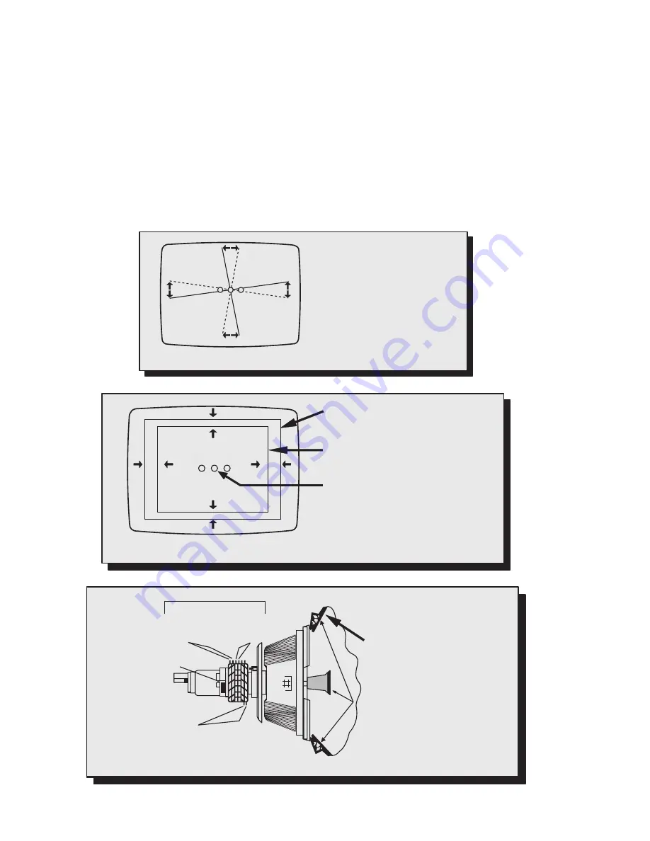
As the yoke is moved
vertically, the rasters
produced by the outside
guns rotate in opposite
directions.
Figure 10.
Vertical Yoke Movement
R
B
B G R
Raster produced from one of the
outside electron beams
Raster from the other side electron
beam
Static convergence magnets are set for
center convergence
As the yoke is moved horizontally, one
raster gets larger while the other gets
smaller
Figure 11.
Horizontal Yoke Movement
R
B
11 o’clock Position
Double sided adhesive tape
3 o’clock Position
7 o’clock Position
6 Pole
Converges
R/B with G
4 Pole
Converges
R with B
Purity/Convergence
Assembly Clamp
Purity Rings Adj. on
Green Raster
Static Convergence Magnets
Yoke Positioning Wedges
for Dynamic Convergence
Figure 12.
Convergence Magnets and Wedges Location


