chassis. Connect the test equipment to the proper ground(hot) or
(cold) when servicing, or incorrect voltages will be measured.
2.1. X-Ray Protection Circuit Check & Adjustments
This test must be performed as final check before the receiver is returned to the customer. If
voltages are out of tolerance, immediate service and correction is required to insure safe
operation and to prevent the possibility of premature componentfailure.
Equipment:
1. Isolation transformer.
2. High voltage meter.
3. D.C. Ammeter
4. Short jumper.
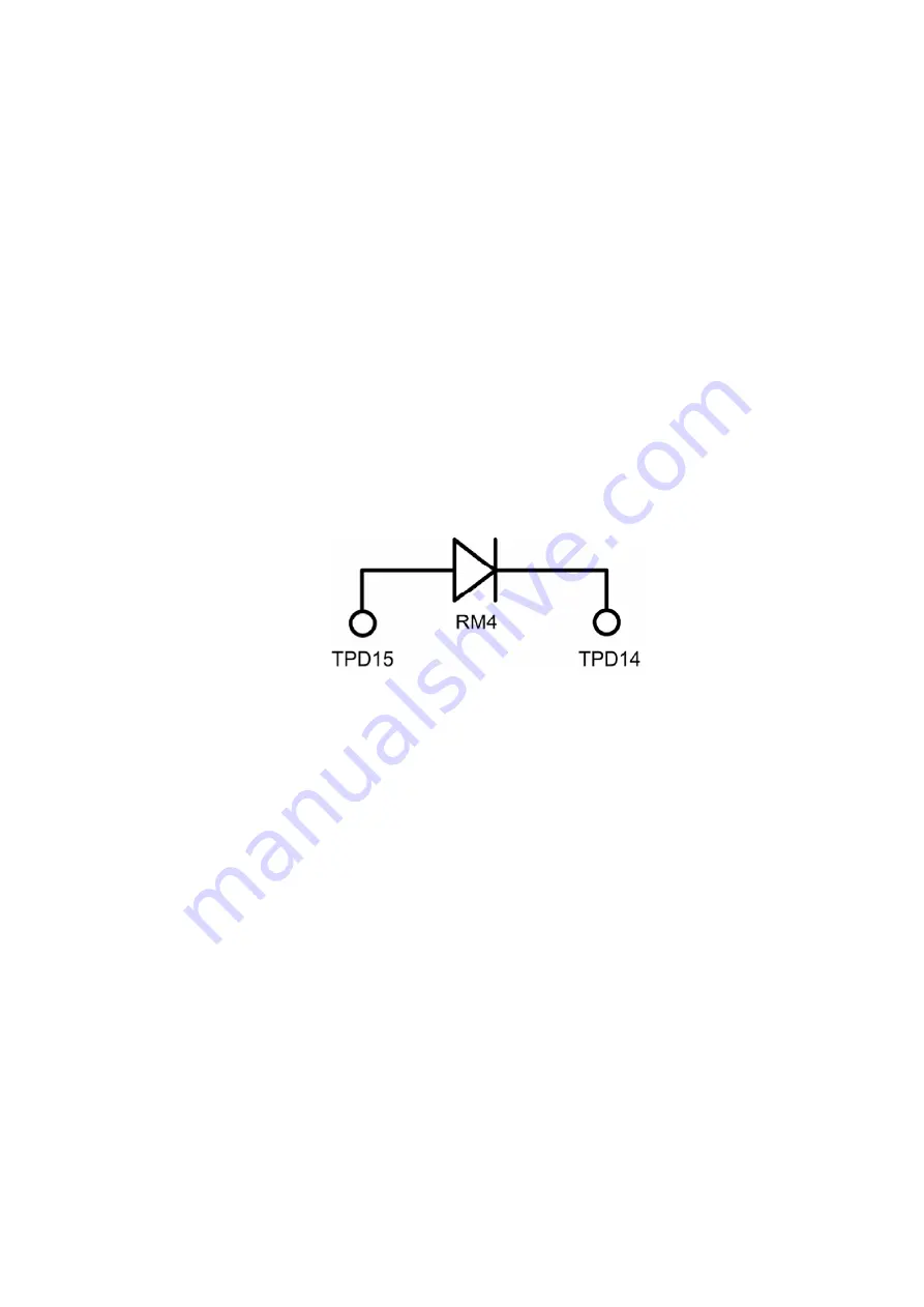
5. HHS jig (See figure below).
Diode Connection Jumper.
Preparation:
1. Make sure the receiver is turned off.
2. Connect the receiver to an isolation transformer.
3. Connect the ammeter serial from the flyback anode lead to the
picture tube anode socket.
4. Prepare short jumper and HHS jig.
Procedure:
1. Connect the short jumper between TPD16 & TPD17.
2. Connect the jumper diode between TPD14 and TPD15 (anode
connected to TPD15 and cathode to TPD14).
3. Apply 75VAC to AC input of isolation transformer.
4. Turn the receiver on.
7
Summary of Contents for CT32E14J - 32" COLOR TV
Page 33: ...13 1 1 C Board Chassis C Board component location 13 1 2 A Board Chassis 33 ...
Page 34: ...13 1 3 A Board Surface mounted components A Board bottom view 34 ...
Page 35: ...35 ...
Page 37: ...37 ...
Page 38: ...17 2 Notas de Esquematicos en Espa ñ ol 38 ...
Page 39: ...39 ...
Page 41: ...19 2 Parts List 41 ...
Page 46: ...C2532 ECA1HM4R7B CAP E 4 7UF 50V 46 ...
Page 49: ...IC3002 MM1501XNRE INT CKT 49 ...
Page 83: ...12 3 Instructional flow chart for service mode continued 26 ...
Page 95: ...Back Cover Removal CT 25L8G CT 25L8UG 38 ...
Page 96: ...14 2 Chassis Components Rear view inside cabinet 39 ...
Page 98: ...14 2 3 CT 20L8 A Board Chassis A Board Top view CT 20L8G 41 ...
Page 99: ...14 2 4 CT 25L8 CT 25L8U A Board Chassis A Board Top view CT 25L8G CT 25L8UG 42 ...
Page 100: ...14 2 5 A Board Surface mounted components A Board bottom view 43 ...
Page 101: ...44 ...
Page 103: ...46 ...
Page 104: ...18 2 Notas de Esquemáticos en Español 47 ...
Page 105: ...48 ...
Page 107: ...20 2 Parts List 50 ...
Page 113: ...D3019 CVS20A120MTA DIODE 56 ...
Page 115: ...L805 EXCELDR35V FERRITE BEAD CT 20G8G CT 20G8SG CT 20L8G 58 ...
Page 124: ...1 2 3 4 5 6 7 8 A B C D E F G H I J A BOARD 1 of 4 TNP2AH047AA AB CT 20L8G CT 20G8G CT 20G8SG ...
Page 125: ...1 2 3 4 5 6 7 8 A B C D E F G H I J A BOARD 2 of 4 TNP2AH047AA AB CT 20L8 CT 20G8 CT 20G8S ...
Page 126: ...1 2 3 4 5 6 7 8 A B C D E F G H I J A BOARD 3 of 4 TNP2AH047AA AB CT 20L8G CT 20G8G CT 20G8SG ...
Page 127: ...1 2 3 4 5 6 7 8 A B C D E F G H I J A BOARD 4 of 4 TNP2AH047AA AB CT 20L8G CT 20G8G CT 20G8SG ...
Page 128: ...1 2 3 4 5 6 7 8 A B C D E F G H I J A BOARD 1 of 4 TNP2AH047FA CT 25L8G CT 25L8UG ...
Page 129: ...1 2 3 4 5 6 7 8 A B C D E F G H I J A BOARD 2 of 4 TNP2AH047FA CT 25L8G CT 25L8UG ...
Page 130: ...1 2 3 4 5 6 7 8 A B C D E F G H I J A BOARD 3 of 4 TNP2AH047FA CT 25L8G CT 25L8UG ...
Page 131: ...1 2 3 4 5 6 7 8 A B C D E F G H I J A BOARD 4 of 4 TNP2AH047FA CT 25L8G CT 25L8UG ...


