background image

2

The following symbols are used in this section.

Pin assignment

Only the thru-beam receiver incorporates the output.

NPN output type

Only the thru-beam receiver incorporates the output.

PNP output type

Only the thru-beam receiver incorporates the output.

Mount the sensor with a tightening torque of 0.5N·m or less.

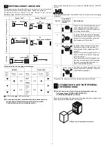
Thru-beam type sensor

1

Set the operation mode switch to the Light-ON mode position (L side).

2

Placing the emitter and the receiver face to face along a straight line.
Move the emitter up, down, left and right to determine where light is
received with the help of the receiver’s operation indicator (orange). Set
the emitter in the middle of this area.

3

Adjust the angle of the emitter by twisting it up, down, left and right.

4

In a similar manner, adjust the angle of the receiver.

5

Check that the stability indicator (green) lights up.

6

Choose the desired operation mode, Light-ON or Dark-ON, with the
operation mode switch.

Retroreflective type sensor

Make sure to mount the sensor and the reflector at least 0.1mm 
apart.

1

Set the operation mode switch to the Light-ON mode position (L side).

2

Placing the sensor and the reflector face to face along a straight line.
Move the reflector up, down, left and right to determine where light is
received the help of the operation indicator (orange). Set the reflector in
the middle of this area.

3

Adjust the angle of the reflector by twisting it up, down, left and right.

4

In a similar manner, adjust the angle of the sensor.

5

Check that the stability indicator (green) lights up.

6

Choose the deisred operation mode, Light-ON or Dark-ON, with the
operation mode switch.

4

I/O CIRCUIT DIAGRAMS

Symbol

Meaning

D

Reverse supply polarity protection diode

Z

D

Surge absorption zener diode

Tr

NPN / PNP output transistor

M12 pigtailed type

Terminal name

M8 connector type

1) +V
2) Not connected
3) 0V
4) Output (see note)

1

2

3

4

1

2

3

4

D

T

r

Z

D

+

-

±10%

100mA max.

Color code of cable with connector

(Brown / 1) +V

(Blue / 3) 0V

(Black / 4)
Output (note)

Load

Internal circuit

Users' circuit

12 to 24V DC

Sensor circuit

D

T

r

Z

D

+

-

±10%

100mA max.

(Brown / 1) +V

(Blue / 3) 0V

(Black / 4) 
Output (note)

Load

12 to 24V DC

Internal circuit

Users' circuit

Color code of cable with connector

Sensor circuit

5

MOUNTING AND ADJUSTING

Sensor mounting 
bracket (optional)

12mm M3 screws 
with washers

Emitter

Receiver

Object to be sensed

Reflector

Sensor

Object to be sensed

Summary of Contents for CX-400 Series

Page 1: ...EN DE ES FR IT CX 400 Instruction Manual Bedienungsanleitung Manual de Instrucciones Manuel d instructions Manuale di istruzione...

Page 2: ...direct contact with water or corrosive gas Take care that the sensor does not come in direct contact with water oil grease or organic solvents such as thinners etc Connector cables for the M12 pigtail...

Page 3: ...ON mode position L side 2 Placing the sensor and the reflector face to face along a straight line Move the reflector up down left and right to determine where light is received the help of the operat...

Page 4: ...indicator Output Sensing condition Output Operation indicator Stability indicator ON Stable light OFF Unstable light OFF Unstable dark ON Stable dark Emitter Receiver Object to be sensed Receiver Emit...
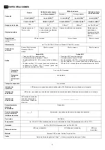
Page 5: ...revention filters are only available for the thru beam type sensor By mounting interference prevention filters two sets of thru beam type sensors can be mounted close together However the sensing rang...

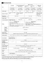
Page 6: ...type NPN open collector transistor Maximum sink current 100mA Applied voltage 30V DC or less between output and 0V Residual voltage 1V or less at 100mA sink current 0 4V or less at 16mA sink current...

Page 7: ...om Rudolf Diesel Ring 2 D 83607 Holzkirchen Germany Phone 49 8024 648 0 URL sunx jp SUNX Limited 4 The sensing range of the diffuse reflective type sensor and the narrowview reflective type sensor is...

Page 8: ...ht durch gewaltsames Verbiegen oder Ziehen Montageorte mit berm ig viel Dampf Staub etc sind ungeeignet Vermeiden Sie auch dass der Sensor korrodierenden D mpfen ausgesetzt wird Der Sensor darf ferner...

Page 9: ...L um den Modus Hell EIN zu aktivieren 2 Platzieren Sie Sensor und Reflektor so dass sie in einer geraden Linie gegen ber liegen Bewegen Sie den Reflektor nach oben unten links und rechts um mit Hilfe...

Page 10: ...anzeige Stabili t tsan zeige EIN Stabiles Licht OFF Instabile Helligkeit OFF Instabile Dunkel heit EIN Instabile Dunkel heit Sender Empf nger Zu erkennendes Objekt Empf n Sender Sensor Reflektor Senso...

Page 11: ...nach vorne abziehen Die Filter zum Schutz vor Lichtinterferenzen stehen nur f r die Einweg Lichtschranke zur Verf gung Um zwei Einweglichtschranken parallel nebeneinander betreiben zu k nnen m ssen I...

Page 12: ...Spannung Max 30V DC zwischen Ausgang und 0V Restspannung max 1V bei 100mA Laststrom max 0 4V bei 16mA Laststrom Typ mit PNP Ausgang PNP Open Collector Transistor Maximaler Laststrom 100mA Angelegte S...

Page 13: ...lnummer die Endung J M8 Steckertypen enthalten in der Modellnummer die Endung Z 3 Die Reichweite und die Objektgr e f r die Reflexions Lichtschranke beziehen sich auf den Einsatz des Reflektors RF 230...

Page 14: ...ensor no entre en contacto directo con agua aceite grasa disolventes org nicos etc Cables con conector para el modelo con conector M12 Cables con conector para el modelo con conector M8 Para el sensor...

Page 15: ...ocar el interruptor de modo de operaci n en la posici n Con Luz lado L 2 Colocar el emisor y el espejo enfrentados a lo largo de una l nea recta Mover el espejo arriba abajo izquierda y derecha para d...

Page 16: ...ndici n de detecci n Salida Indicador de operaci n Indicador de estabilidad ON Luz estable OFF Luz inestable OFF Oscuridad inestable ON Oscuridad estable Espejo Sensor Objeto detectable Emisor Recepto...

Page 17: ...sensores de tipo barrera Colocando los filtros de prevenci n de interferencia mutua se pueden montar dos juegos de sensores de barrera uno junto a otro Sin embargo se reduce el rango de detecci n Los...

Page 18: ...6mA Salida PNP Transistor PNP en colector abierto Corriente m xima fuente 100mA Tensi n aplicada 30V DC o menos entre la salida y V Tensi n residual 1V o menos para una corriente fuente de 100mA 0 4V...

Page 19: ...N FILTROS POLARIZADORES 2 Las referencias con el sufijo J indican que se trata del modelo con conector M12 El sufijo Z indica que es el modelo con conector M8 3 El rango de detecci n y el objeto a det...

Page 20: ...e des diluants etc C bles avec connecteur pour la version queue de cochon M12 C bles avec connecteur pour la version avec connecteur M8 Deux jeux de c bles sont n cessaires pour le capteur version bar...

Page 21: ...l autre 1 S lectionner le mode Light ON en tournant le commutateur de mode de fonctionnement jusqu L 2 Placer le capteur et le r flecteur face face en ligne droite D placer le r flecteur vers le haut...

Page 22: ...teur de fonction nement Indica teur de stabilit ON Lumi re stable OFF Lumi re instable OFF Obscu rit insta ble ON Obscu rit stable R flecteur Capteur Objet d tecter Emetteur R cepteur Objet d tecter R...

Page 23: ...e suppression des interf rences sont disponibles uniquement pour la version barrage Les filtres de suppression des interf rences permettent d installer deux jeux de capteurs version barrage l un c t d...

Page 24: ...ant de source maxi 100mA Tension utilis e 30V DC maxi entre sortie et V Tension r siduelle 1V maxi avec courant de source de 100mA 0 4V maxi avec courant de source de 16mA Fonctionne ment de la sortie...

Page 25: ...F AVEC FILTRES POLARISANTS 2 Les r f rences avec le suffixe J d signent les versions queue de cochon M12 Le suffixe Z d signe la version avec connecteur M8 3 La port e et l objet d tectable de la vers...

Page 26: ...as corrosivi Assicurarsi che il sensore non entri in contatto diretto con acqua oli grassi o solventi organici quali diluenti ecc Cavi di collegamento per il tipo M12 a spirale Cavi di collegamento pe...

Page 27: ...lato L 2 Posizionare sensore e riflettore l uno di fronte all altro in modo che siano allineati Muovere il riflettore verso l alto e il basso verso sinistra e destra per accertare con l aiuto dell in...

Page 28: ...leva mento Uscita Indica tore di funziona mento Indica tore di stabilit ON Luce sta bile OFF Luce instabile OFF Buio instabile ON Buio sta bile Emettitore Ricevitore Oggetto rilevabile Ricevitore Emet...

Page 29: ...pressione di interferenze sono disponibili solo per il sensore di tipo a sbarramento Per montare l uno acccanto all altro due kit di sensori di tipo a sbarramento si devono montare filtri di soppressi...

Page 30: ...cata max 30V DC fra uscita e V Tensione residua max 1V con corrente di sorgente 100mA max 0 4V con corrente di sorgente 16mA Funziona mento uscita Light ON o Dark ON Protezione da corto circuito Incor...

Page 31: ...r informazioni pi dettagliate vedi pagina 4 sezione 8 SENSORE A CATARIFRANGENTE CON FILTRI POLARIZZATI 2I numeri di modelli con il suffisso J indicano il tipo M12 a spirale Il suffisso Z indica il sen...

Reviews: