background image

VOLUME

MENU

MUTE

MODE

NAVI

NAVIGATION

ASPECT

P·MODE

POWER

ASP

ENTER

CY-VMC7000U

IN-DASH 7 WIDE COLOR LCD MONITOR / CD PLAYER

DISC/BAND

TRACK/

YUNE

ENTER

29

CY-VMC7000U

20

E

N

G

L

I

S

H

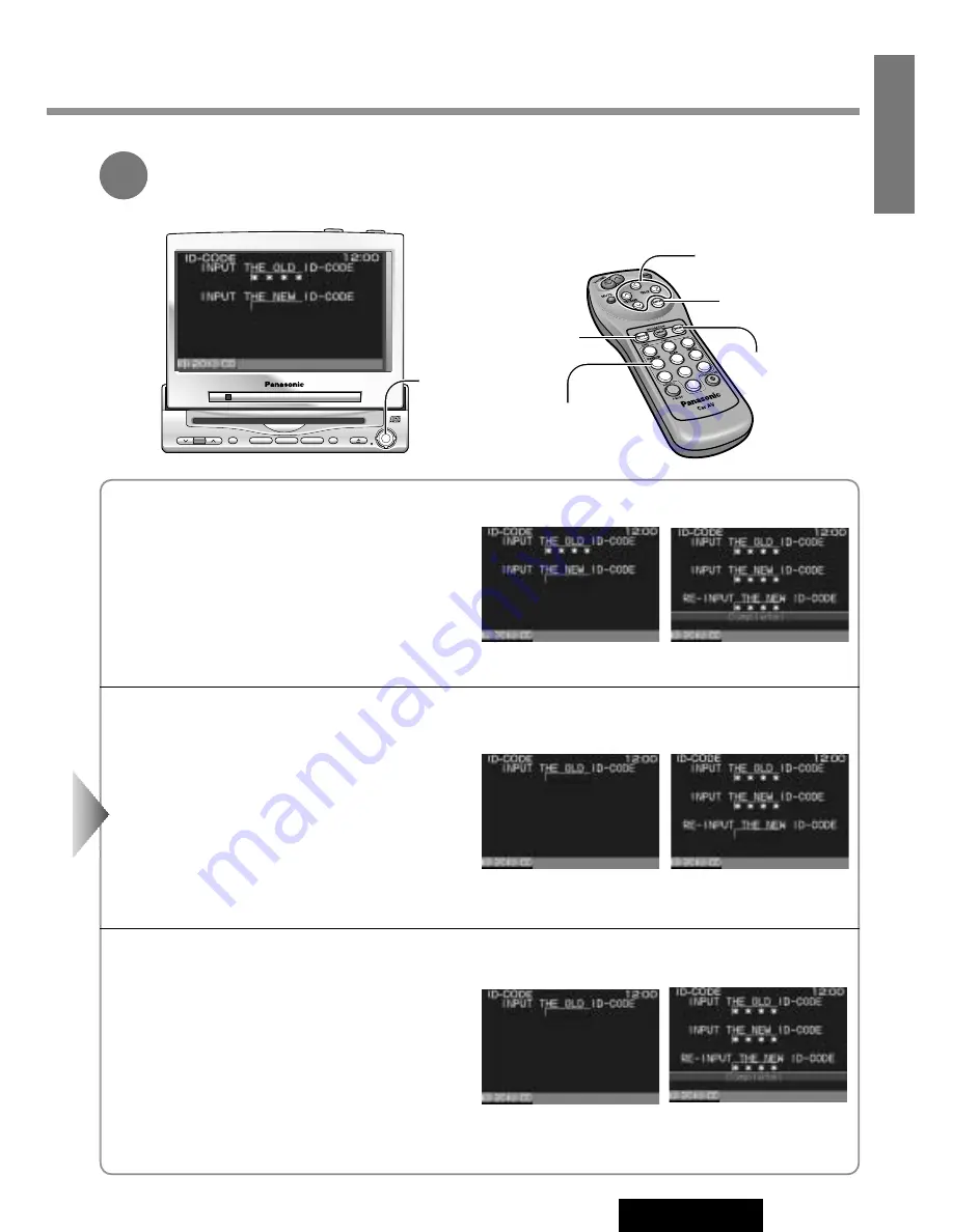
How to Set Your ID Code (For the First Time)

q

Enter an ID code of 4 digits using the buttons 

[0]

to

[9]

on the remote control.

Note:

When you are setting your ID code for the  

first time, it is not  necessary to enter the old ID code.

w

Enter the ID code of 4 digits again using the buttons

[0]

to 

[9]

on the remote control.

How to Change Your ID Code 

q

Enter the preset (old) ID code of 4 digits using the
buttons 

[0]

to 

[9]

on the remote control. If the

wrong ID code is entered, a new ID code cannot be
registered.

w

Enter a new ID code of 4 digits using the buttons 

[0]

to 

[9]

on the remote control.

e

Enter the new ID code of 4 digits again using the
buttons 

[0]

to 

[9]

on the remote control.

How to Cancel the Known ID Code 

q

Enter the preset (old) ID code of 4 digits using the
buttons 

[0]

to 

[9]

on the remote control. If the

wrong ID code is entered, it is not possible to cancel
the ID code function.

w

Press and hold 

[ENTER]

until display the

"Complete!".

The ID code cancelling procedure is completed. The unit now works without an ID code.

Note: 

Press 

[MODE]

to return to the regular mode.

3

[ENTER]

1

2

3

4

5

6

7

8

9

A

0

1

2

3

4

5

6

7

8

9

0

[

}

] [

{

]

[

]

] [

[

]

(Select)

[ENTER]

[MODE]

[MENU] 

[0] 

to 

[9]

(ID code input)

Enter an ID code by using the remote control.

Note:

Should your unit ever require service, cancel your

ID code before sending for repair.

Summary of Contents for CY-VMC7000U

Page 1: ...ion of America One Panasonic Way Secaucus New Jersey 07094 http www panasonic com Panasonic Sales Company Division of Matsushita Electric of Puerto Rico Inc PSC Ave 65 de Infanteria Km 9 5 San Gabriel Industrial Park Carolina Puerto Rico 00985 http www panasonic com Panasonic Canada Inc 5770 Ambler Drive Mississauga Ontario L4W 2T3 www panasonic ca ...

Page 2: ...this manual for future use Prière de lire ces instructions attentivement avant d utiliser le produit et garder ce manuel pour l utilisation ultérieure Lea con atención estas instrucciones antes de utilizar el producto y guarde este manual para poderlo consultar en el futuro Operating Instructions Manuel d instructions Manual de Instrucciones VOLUME MENU MUTE MODE NAVI NAVIGATION ASPECT P MODE POWE...

Page 3: ... help with identifica tion in case of theft MODEL NUMBER CY VMC7000U SERIAL NUMBER DATE PURCHASED FROM CAUTION THIS PRODUCT IS A CLASS I LASER PRO DUCT USE OF CONTROLS OR ADJUSTMENTS OR PERFORMANCE OF PROCEDURES OTHER THAN THOSE SPECIFIED HEREIN MAY RESULT IN HAZARDOUS RADIATION EXPOSURE DO NOT OPEN COVERS AND DO NOT REPAIR YOURSELF REFER SERVICING TO QUALI FIED PERSONNEL WARNING TO REDUCE THE RIS...

Page 4: ...E POUR RÉDUIRE LES RISQUES D INCENDIE OU D ÉLECTROCUTION N EXPOSEZ PAS CET APPAREIL À LA PLUIE OU À L HUMIDITÉ AFIN DE PRÉVENIR TOUT RISQUE D INCENDIE UTILISER UNIQUEMENT LES COMPOSANTS FOUR NIS Produits laser Longueur d onde 780 nm Puissance du laser Aucune radiation dangereuse n est émise avec la protection de sécurité ATTENTION OBSERVEZ LES LOIS ET REGLEMENTS DE VOTRE DEPARTEMENT PROVINCE OU PA...

Page 5: ... of the screen is automatically adjusted in response to surrounding brightness External extension terminal Two video input on the control unit side You can connect a car navigation system DVD player VCR camcorder and rear view camera with this unit if they have video output type terminal One video output on the control unit side You can connect another monitor for passengers in the rear seat You c...

Page 6: ... Sound from Auxiliary Devices 18 Car navigation system DVD player VCR camcorder rear view camera and rear seat monitor Useful Functions 22 Aspect ratio change User Settings 24 Monitor position navigation setup rear view camera setup clock setting ID code setting button operation sound and video control setting Display Settings 32 Dimmer contrast brightness color and tint Installation Guide 34 Step...

Page 7: ...ters Do not attempt to disassemble or adjust this precision product Please refer to the Servicenter list included with this prod uct for service assistance For Installation The product should be installed in a horizontal position with the front end up at a convenient angle but not more than 30 WARNING TO AVOID RISK OF SERIOUS INJURY OR POSSIBLE VIOLATION OF LAWS NOT FOR USE WHERE VISIBLE TO DRIVER...

Page 8: ... off Turn on the power again and enter a correct ID code in this case Caution Record your registered ID code and keep it in a secure location If you forget it you will be unable to use the unit In case that you can not operate the unit because of forgetting the ID code please consult your nearest Panasonic Servicenter Picture might not be displayed or it might take more time than usual to display ...

Page 9: ...h tape or the like Contact with metallic objects or other batteries can cause ignition or rupture If the batteries are used in the wrong way there is the danger of liquid leakage rupture injuries and failure Insert bat teries correctly with respect to their positive and negative ends Caution When decayed follow the rules and regulations of your country Caution Improper use of batteries may cause o...

Page 10: ... navigation a page 18 A ASPECT Selects the aspect ratio a page 22 Display Unit VOLUME MENU MUTE MODE NAVI NAVIGATION ASPECT P MODE POWER ASP ENTER CY VMC7000U IN DASH 7 WIDE COLOR LCD MONITOR CD PLAYER DISC BAND TRACK YUNE Dimmer sensor a page 32 Remote control sensor MENU Shows the menu screen a page 24 Shows the rear monitor setting menu a page 20 VOLUME Adjusts the sound volume a page 14 MUTE M...

Page 11: ...und level for each source is stored in memory OFF Press MODE POWER again for more than 2 seconds On the display unit Press PWR again or MODE again for more than 2 seconds On the remote control Default Volume 24 Setting Range 0 to 40 VTR1 VTR2 CD Player Turn the key in the ignition until the accessory indicator lights CLOSE Press OPEN CLOSE again After return the lateral angle to the neutral positi...

Page 12: ...utomatically closed if no operation is performed for about 60 seconds Vertical angle TILT and front rear position data are saved in the memory so when the display unit is drawn out next it is automatically set at the angle and in the position adjusted before After adjusting its angle also adjust the brightness to make it easy for you to watch a page 32 The display position can also be set on the m...

Page 13: ...e power on Track Selection TRACK Next track TRACK Beginning of the current track Previous track Press twice Track Search Press and hold TRACK Fast forward TRACK Fast backward CD Player Label Side Disc Eject Press u to stop playback and eject the CD Cautions Do not use irregularly shaped CDs Do not insert foreign matter into the disc slots MODE TRACK Notes You can play a CD even if the monitor is c...

Page 14: ...vailable tracks are played in a random sequence Press 4 RANDOM again to cancel Scan Play The first 10 seconds of each track plays in sequence Press 5 SCAN again to cancel With the scanning of all tracks over the original program starts playing from the beginning Press 4 RANDOM Press 5 SCAN Press 6 REPEAT 1 2 3 4 5 6 7 8 9 A 0 4 1 2 3 4 5 6 7 8 9 A 0 5 1 2 3 4 5 6 7 8 9 A 0 6 ...

Page 15: ... screen according to the terminal actually connected to the car navigation system a page 24 DVD Player Preparation Connect a DVD player a page 44 VOLUME MENU MUTE MODE NAVI NAVIGATION ASPECT P MODE POWER ASP ENTER CY VMC7000U IN DASH 7 WIDE COLOR LCD MONITOR CD PLAYER DISC BAND TRACK YUNE MODE NAVI MODE NAVI NAVIGATION 1 2 3 4 5 6 7 8 9 A 0 MODE NAVI NAVIGATION ...

Page 16: ...audio output RGB car navigation RGB input cord VTR1 IN VTR2 IN Panasonic Car Navigation System CY VMC7000U Control Unit CY VMC7000U Display Unit Example Other brand s car navigation system CY VMC7000U Control Unit VTR1 IN VTR2 IN Example Press MODE to change to the VTR1 or VTR2 mode Select the same mode VTR1 or VTR2 as the terminal that is connected to a DVD video player VTR1 IN or VTR2 IN Note Th...

Page 17: ...ion Connect a VCR or Camcorder a page 46 Rear View Camera Preparation Connect a rear view camera and a reverse lead a page 47 Select a terminal in the CAMERA IN screen according to the terminal actually connected to the rear view camera a page 26 1 2 3 4 5 6 7 8 9 A 0 VOLUME MENU MUTE MODE NAVI NAVIGATION ASPECT P MODE POWER ASP ENTER CY VMC7000U IN DASH 7 WIDE COLOR LCD MONITOR CD PLAYER DISC BAN...

Page 18: ...2 mode always come out VTR2 VTR1 AUTO Rear Monitor Setting Menu Shift the transmission gear into the reverse position The display shows a picture from the rear view camera Notes You can see a picture from the rear view camera even if the power of the display unit is inactivated You can a see picture from the rear view camera if you change the mode to the same one VTR1 or VTR2 as the terminal to wh...

Page 19: ...ns Aspect Ratio for VTR Mode Default Normal Mode 4 types 1 2 3 4 5 6 7 8 9 A 0 A VOLUME MENU MUTE MODE NAVI NAVIGATION ASPECT P MODE POWER ASP ENTER CY VMC7000U IN DASH 7 WIDE COLOR LCD MONITOR CD PLAYER DISC BAND TRACK YUNE ASP ASP ASPECT A ASPECT ...

Page 20: ...screen is extended horizontally as a whole to the aspect ratio of 16 to 9 The extension ratio is the same at any point of the screen Zoom The screen is fully extended at the normal aspect ratio of 4 to 3 The top and bottom of the screen are slightly cut Just The screen is extended horizontally to the aspect ratio of 16 to 9 The extension ratio increases toward the right and left ends of the screen...

Page 21: ... YUNE MENU MODE 24 CY VMC7000U 15 E N G L I S H User Settings Monitor Position Default TILT 3 SLIDE Front Setting range TILT 1 to 5 SLIDE Front Rear Navigation Set Up Default Navigation input RGB Speaker setting AUTO Note You can set the Navigation speaker setting when RGB is selected on Navigation input USER TILT SLIDE NAVI SETUP 1 2 Press MENU to display the main menu q Press or to select USER P...

Page 22: ...s For smooth adjustment make sure to first return the lateral angle to the neutral position and then adjust the tilt angle Front rear position REAR and tilt angle 5 cannot be selected at the same time Tilting angle adjustment Front rear position REAR FRONT 5 4 3 2 1 Navigation Input Connected to the RGB input cord or a car navigation system not connected Connected to the VTR1 IN Connected to the V...

Page 23: ...R ASP ENTER CY VMC7000U IN DASH 7 WIDE COLOR LCD MONITOR CD PLAYER DISC BAND TRACK YUNE MENU MODE 26 CY VMC7000U 17 E N G L I S H User Settings continued Clock Setting Default Clock display OFF USER CLOCK Rear View Camera Set Up Default OFF CAMERA IN Select Select Select 1 2 Press MENU to display the main menu q Press or to select USER Press or to select an item w Press ENTER to set Select ENTER M...

Page 24: ...zero seconds The clock display blinks once and clock starts SEC RESET Unconnected Connected to the VTR1 IN Connected to the VTR2 IN VTR2 VTR1 OFF Notes Press MODE to return to the regular mode The display returns to the previous one if there is no operation for more than 60 seconds after changing to the setting adjusting menu 3 q Press or to select and adjust w Press ENTER to set Select and Adjust...

Page 25: ... re connected It is elec tronically locked so that a thief could not use the stolen unit unless that person knows the code you have set The ID code operation must be performed only by the person whom the unit belongs to Generally it is not necessary to enter the ID code each time when using the unit if it has never been disconnected from the main power supply car battery USER ID CODE Caution Recor...

Page 26: ...e is entered a new ID code cannot be registered w Enter a new ID code of 4 digits using the buttons 0 to 9 on the remote control e Enter the new ID code of 4 digits again using the buttons 0 to 9 on the remote control How to Cancel the Known ID Code q Enter the preset old ID code of 4 digits using the buttons 0 to 9 on the remote control If the wrong ID code is entered it is not possible to cancel...

Page 27: ...R CD PLAYER DISC BAND TRACK YUNE MENU MODE 30 CY VMC7000U 21 E N G L I S H User Settings continued Button Operation Sound Default ON etc Video Control Setting This Video Control Setting is required when you connect a Panasonic car navigation sys tem with a built in DVD player not available yet Default VTR1 USER Select Select 1 2 Press MENU to display the main menu q Press or to select USER Press o...

Page 28: ...elect a terminal connected to the DVD output terminal of a Panasonic car navigation system with a built in DVD player not available yet through an RCA cord Notes Press MODE to return to the regular mode The display returns to the previous one if there is no operation for more than 60 seconds after changing to the setting adjusting menu 3 q Press or to select w Press ENTER to set Select ENTER 1 2 3...

Page 29: ...BAND TRACK YUNE MENU MODE 32 CY VMC7000U 23 E N G L I S H Display Settings SCREEN DIMMER Dimmer Default AUTO CONTRAST Contrast Default 0 Setting range 15 to 15 BRIGHT Brightness Default 0 Setting range 15 to 15 COLOR Color Default 0 Setting range 15 to 15 TINT Tint Default 0 Setting range 15 to 15 Select Select Select Select Select Select 1 2 Press MENU to display the main menu q Press or to selec...

Page 30: ...een black and white Decrease the contrast between black and white Darken Lighten Deepen the depth of color on the display Lighten the depth of color on the display Emphasize green in the color image Emphasize red in the color image Notes Press MODE to return to the regular mode The display returns to the previous one if there is no operation for more than 60 seconds after changing to the setting a...

Page 31: ...label the car wires Connect the car wires to the wires of the power connector Install the unit in the dashboard Check the operation of the unit If you encounter problems please consult your nearest professional installer Caution This unit operates with a 12 volt DC nega tive ground auto battery system only Do not attempt to use it in any other system Doing so could cause serious damage Installatio...

Page 32: ...volt DC negative ground vehicle This unit is only for use with a 12 volt DC negative ground vehicle It cannot be used in large trucks or diesel vehicles which are 24 volt DC vehicles If it is used in the wrong type of vehicle it may cause a fire or an accident Caution Use the specified fuse Be sure to always use the specified fuse If a fuse other than the specified fuse is used it may cause a fire...

Page 33: ...s The connection diagram B page 42 shows the proper connections and color coding of the leads We strongly recommend that you test the unit before making a final installation You can set the unit on the floor and make tempo rary connections to test the unit Use electrical tape to cover all exposed wires Important Connect the red power lead last after you have made and insulated all other connection...

Page 34: ...ve the transportation brackets before use installation Use Binding Head Screws M5 x 6 mm for installation Be careful not to lose these Binding Head Screws Display Unit Binding Head Screws M5 x 6 mm Binding Head Screws M5 x 6 mm Transportation Bracket Transportation Bracket Mounting the Display Unit Precautions This unit should be professionally installed In case of difficulty please consult with y...

Page 35: ... the Mounting Springs e to the display unit 2 9 Display Unit Control Unit Connecting Cord Secure the rear of the unit Fix the rear of the unit to the car body by either method a or b shown at right after fixing Power Connector 6 and Display Unit Control Unit Connecting Cord 9 Installation Procedures When using Mounting Collar w w Mounting Collar Dashboard Tab Fastening the Mounting Collar The tabs...

Page 36: ...g Mounting Collar w Use the brackets supplied with your car when mounting this unit The bracket shape and mounting method vary with car manufacturers car types and manufacturing year Please consult your nearest Panasonic Servicenter for details Select mounting screws according to the hole positions and hole shape of the bracket 1 Flat Head Screw M5 x 6 mm 4 pieces 2 Binding Head Screw M4 x 3 mm 4 ...

Page 37: ...in Control Unit 5 Velcro Tape Carpet Note Some carpet materials may not be suit able for this mounting method In this case please contact your nearest Panasonic Servicenter for installation Mounting the Control Unit Installation Guide continued Use the supplied Spacer 3 if mounting hole of your car is shaped like below Display Unit 3 Spacer 4 Double Faced Adhesive Tape 0 Binding Head Screw M5 x 6 ...

Page 38: ...es Before mounting the speaker wipe a drop of water dust and an oil stain off from the place where the speaker should be mounted to enhance adhesive strength Cautions Do not install the speaker in a location which obstructs operation of the air bag or other safety equipment Do not leave a credit card or other magnetic cards near the speaker to avoid damaging the cards Mounting the Speaker To Remov...

Page 39: ...9 Display Unit Control Unit Connecting Cord REMOTE OUT CY VMC7000U Display Unit Rear Use a Reverse Extension Cord 7 if needed 42 CY VMC7000U 33 E N G L I S H Electrical Connections Cautions This product is designed to operate off a 12 volt negative ground battery system To prevent damage to the unit be sure to follow the connection diagram below Remove approx 1 4 5mm of protective covering from th...

Page 40: ...o not connect the AV Control Unit CA TU7000U Connect AV control unit with receiver CA TU7000U Cautions Ask a qualified service person for installation and wiring The installation and wiring of this unit requires special skills and experience For safety ask the store where you pur chased it to perform installation and wiring Do Not Disassemble or Modify Do not disassemble or modify the unit Do not ...

Page 41: ...6 Power Connector Pre Out Cord PRE OUT RCA Cord Option RCA Cord Option RCA Cord Option R Red L White Video Yellow R Red R Red Video Yellow L White L White RCA Cord Option 9 Display Unit Control Unit Connecting Cord Electrical Connections continued Example Connection with DVD Player Receiver CQ DVR909U and Rear Seat Monitor ...

Page 42: ...Pre Out Cord Front Power Connector Supplied to CQ DVR909U VTR OUT Video Yellow DVD Player Receiver CQ DVR909U Rear Seat Monitor Power Amplifier Unit Supplied to CQ DVR909U R Red Video Yellow L White Audio Left Right Video output Note Refer to the operating instructions for the connected devices in addition ...

Page 43: ...ake connection lead w The Clip Connector 8 is connected to the power source side lead of the parking brake lever Comes up to this point Side Brake Parking Brake Connection Lead Blue yellow stripe Power Source Side Lead Caution For safety be sure to ask your nearest professional installer to do this connection CY VMC7000U Control Unit Front R Red R Red Video Yellow Video Yellow L White L White Audi...

Page 44: ... reverse lamp Take it out of the back of the tail lamp mount Connecting the Reverse Lead In case using an optional rear view camera the reverse lead must be connected Connect the reverse lead violet white stripe to the posi tive lead of the reverse lamp the lamp with a clear lens that lights when the transmission gear is shifted into the reverse position Notes Connect the reverse lead after cuttin...

Page 45: ...eck Remedy No power No sound Condensation dew aWait for a while before use Speakers setting is set to OFF aSet it to other than OFF Cables are not correctly connected aConnect cables correctly Mute is set to ON aSet it to OFF The volume is adjusted to zero aRaise the volume Fuse is burnt aCall the store where you purchased the unit or your nearest Panasonic Servicenter see the attached sheet and a...

Page 46: ... mounting parts referring to the section on Installation Mounting angle is over 30 degrees aAdjust mounting angle to less than 30 degrees CD is dirty aClean CD referring to the section on Notes on CD CD is dirty aClean CD referring to the section on Notes on CD CD is upside down aPlace CD in the correction direction the label side up CD is inside but no sound CD sound skips tone quality is low Sou...

Page 47: ...tion of a DVD player is not correct aConnect it correctly Input setting of a car navigation system is not correct aMake the input setting correct The connection of a car navigation system is not correct aConnect it correctly Symptom Check Remedy The brightness of the screen is not stable This is a characteristic of liquid crystal panels and is not a problem The screen is not adjusted properly aMak...

Page 48: ...r the nearest Panasonic Servicenter to ask for repairs Disc has scratches aCheck disc Disc is dirty or is upside down aCheck disc Symptom Check Remedy Buttons are invalid for operation Remote control is in the wrong direction aDirect the remote control at remote control sensor on the display unit Batteries have run down aReplace the batteries Wrong batteries aCheck the batteries Battery polarities...

Page 49: ...stitutes or fuses with a higher rating or connecting the product directly without a fuse could cause fire or damage to this unit If the replacement fuse fails contact your nearest Panasonic Servicenter for service Reset Switch Reset switch Insert a hard slender stick into the hole and push the switch The unit returns to the default state when the trouble is reset Remember the data and settings sto...

Page 50: ...Benzine Thinner Clean dirt by wiping lightly with a soft cloth When the unit is dirty wipe the surface of the display using Wiping Cloth an accessory to the unit Without a Wiping Cloth When the unit is dirty wipe with a well wrung cloth dipped in a liquid dishwashing detergent neutral diluted with water and then go over the same surface with a dry cloth Since there is the possibility of water drop...

Page 51: ... perimeter These may cause malfunction Remove the rough edges using a pencil etc Music agsjbc ujniu imnmk bhxujk kkmj ibi abcde Music agsjbc ujniu imnmk bhxujk kkmj ibi abcde Label side Do not use irregularly shaped CDs Right Wrong Rough edge A playable CD R disc is only a CD R disc on which sound was recorded Some recorded CD R discs by using CD recorder are not playable because of their characte...

Page 52: ... 1 16 x 3 7 16 x 6 15 16 154 x 87 x 177 mm Number of Pixels 336 960 pixels 234 vertical x 480 horizontal x 3 Valid Pixel Ratio Over 99 99 Display Method Transparent color filter format Drive Method TFT Thin Film Transistor active matrix format Light Source Internal light Built in small fluorescent lamp CD Player Sampling Frequency 8 times oversampling DA Converter MASH 1 bit 4 DAC System Error Cor...

Reviews: