ー
157
ー
Installation Instructions
Communication adaptor
4
Setting the Communication Adaptor board
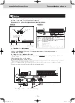
The switches on the board control the adaptor numbers, turn the inter-unit control wiring connection on and off, and control other settings.
(1) Switch operation overview
4
3
D
8
D
D4
D5
D6
D7
9
S
6
S
S8
S7
D1
D2
UP DOWN SET
HOME
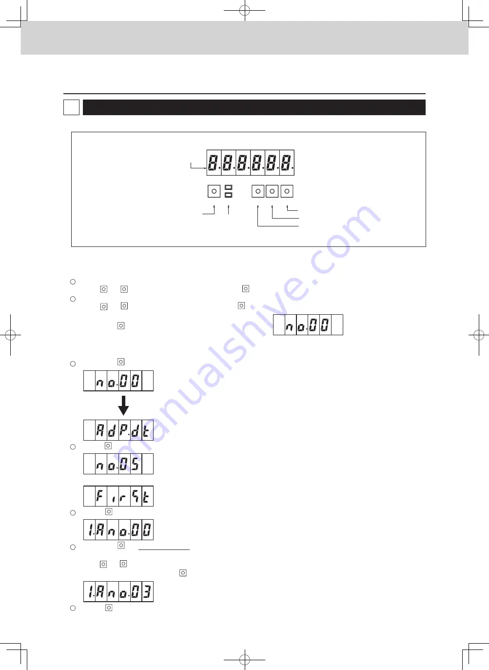
7-segment LED
Home key
Monitor LED
D1: red
D2: green
Set key
Down key
Up key
Item selection
Use the
UP
and
DOWN
keys to find the desired item, then press the
SET
key to select.
Changing the settings
Use the
UP
and
DOWN
keys to change the setting, then press the
SET
key to confirm.
Hold down the
HOME
key for at least two seconds to reset to the default setting
(Any settings in progress will be
lost.)
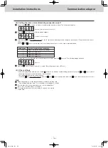
(2) Adaptor number setting procedure
Hold down the
HOME
key for at least two seconds so the initial display shows as follows:
(no.00)
After 2 seconds
(AdP.dt)
Press the
UP
key five times so the following display appears:
(no.05)
This automatically switches to the below display after 2 more seconds. (Operation is not necessary.)
(FirSt)
Press the
SET
key so the below display appears. (Only the green monitor LED is on.)
(1.Ano.00) (Factory setting)
Hold down the
SET
key for at least 1 second so the “00” part blinks, indicating that the setting can be changed. (The green and red monitor
LEDs are both on.)
Use the
UP
and
DOWN
keys to set the adaptor number.
For example, to set number 3, press the
UP
key three times. The following will display:
(1.Ano.03)
Press the
SET
key for at least 1 second to confirm. (Only the green monitor LED is on.)
1
2
1
2
3
4
5
Turn on the Power switch(S1) on the board.
TGR-318_ENG.indb 157
2017/04/06 10:44:43

