2.
How to install the board
・
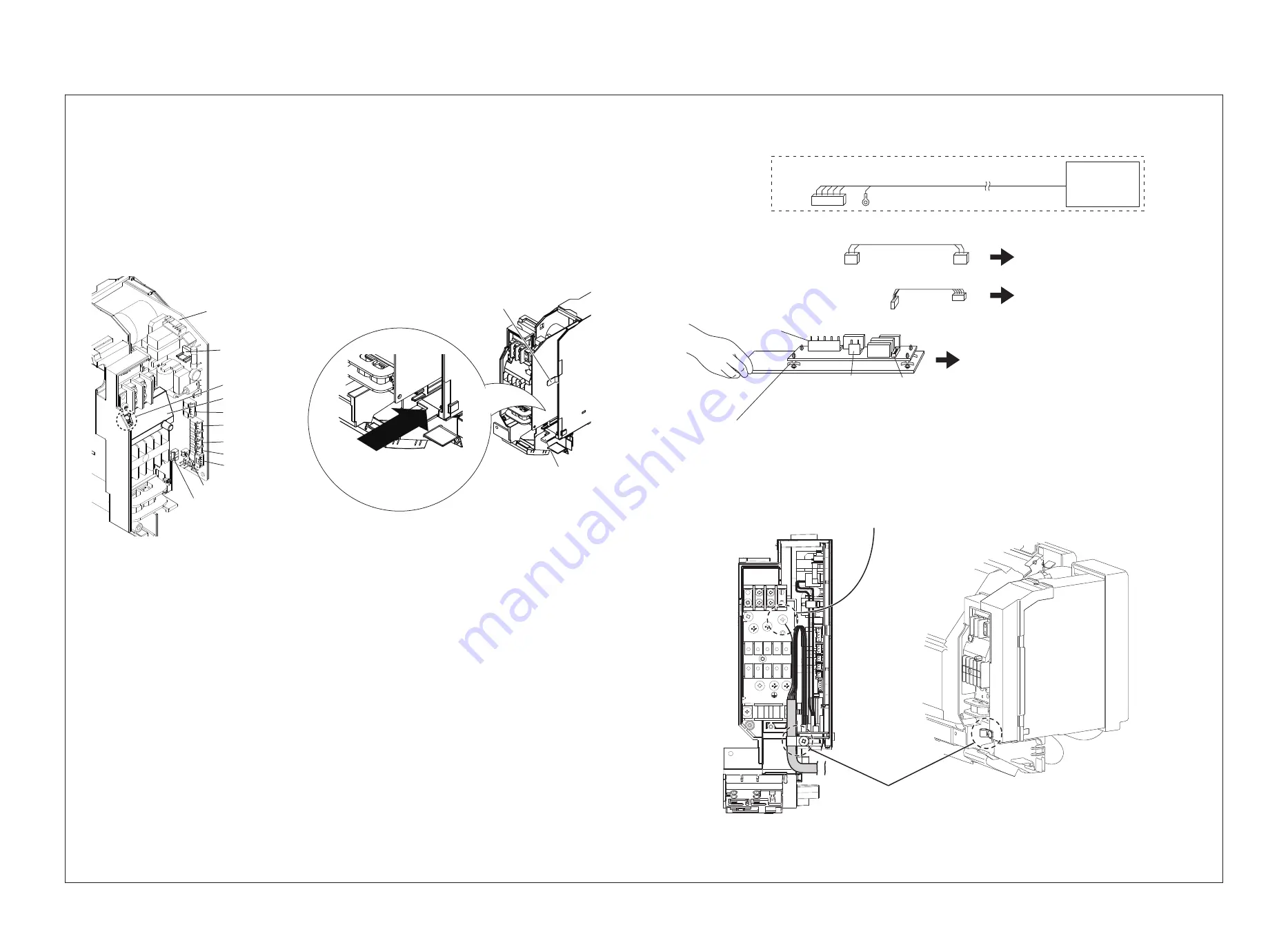
Disconnect the CN033 (White), CN103 (Green), CN102 (Red), CN100 (White), CN082 (White)
,
CN104 (Yellow) connectors from the indoor control PCB and take out the indoor control PCB. (Fig.5)
* When you take out the indoor control PCB, lift the tab holding the indoor control PCB. (Fig.6)
・
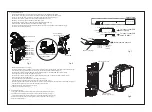
Connect the 3P connector (yellow) of the power cables (supplied part
②
) to the
CN309 OP1 connector (yellow) on the indoor control PCB. (Fig.5)
・
Connect the 5P connector (black) of the signal output cables (supplied part
③
) to
the CN081 3WAY connector (black) on the indoor control PCB. (Fig.5)
・
Connect the removed connectors to their original positions on the indoor control PCB and insert the PCB. (Fig.5)
* Be sure to connect all the connectors.
3P Yellow
To indoor control PCB
OP1(CN309)
3P White
Power cables (supplied part
②
)
5P Black
To indoor control PCB
3WAY (CN081)
6P White
Signal output cables (supplied part
③
)
Optional parts
Solenoid valve kit
9P Red
CN003
9P Red
Spacers (4 locations)
OPTION/3WAY
(CN001)
6P White
POWER
(CN002)
3P White
Board Insertion direction
Fig.7
Fig.8
Protective ground screw
Clamp position for
Solenoid valve kit wiring
3.
How to attach the grille
・
Fit the grille to the three tabs on the upper part of the frame and attach the grille. (Fig.3)
・
Press the grille to its original position. Attach six screws and two screw covers. (Fig.1)
* For the screws on the front, attach screws in turn from the electrical component box side.
・
Warp the lower flap and fit the pins to the grooves on the grille to attach the flap. (Fig.2)
・
Close the front panel. (Fig.1)
・
Clamp the wiring from the solenoid valve kit. (Fig.8)
・
Connect the solenoid valve kit ground wire to the indoor unit ground wire mounting position. Also connect the 9P connector (red)
of the solenoid valve kit to the CN003 9P connector (red) on the solenoid valve control PCB. (Fig.7, 8)
・
Connect the 3
・
Remove the screw and the cover.(Fig.5)
P connector (white) of the power cables (supplied part
②
) to the CN002 POWER connector (white)
on the solenoid valve control PCB (supplied part
①
) (Fig.7)
・
Connect the 6P connector (white) of the signal output cables (supplied part
③
) to the CN001 3WAY connector (white)
on the solenoid valve control PCB.(Fig.7 )
・
Insert the solenoid valve control PCB into its mounting position. (Fig.6)
* Pay attention to the insertion direction of the solenoid valve control PCB. (Fig.7)
・
Attach the screw and the cover.(Fig.5)
r.
・
Hook the upper tab of the electrical component box cover to the electrical component box first, and then fit the lower tab. (Fig.4, 6)
* Pay attention not to catch the wires in the electrical component box cove
Solenoid Valve Control PCB
mounting position
Lower tab
Tab for holding
Indoor control PCB
Fig.6
CN309(Yellow)
CN081(Black)
CN104(Yellow)
CN102(Red)
CN103(Green)
CN033(White)
CN082
Cover
Screw
(White)
CN100(White)
Indoor control PCB
Fig.5
Printed in Japan 85464369394010


