


Optional Controller
Manual of Controller
2
- 26
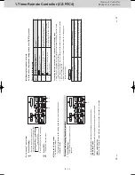
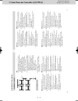
1. Timer Remote Controller (CZ-RTC4)
23
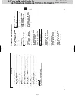
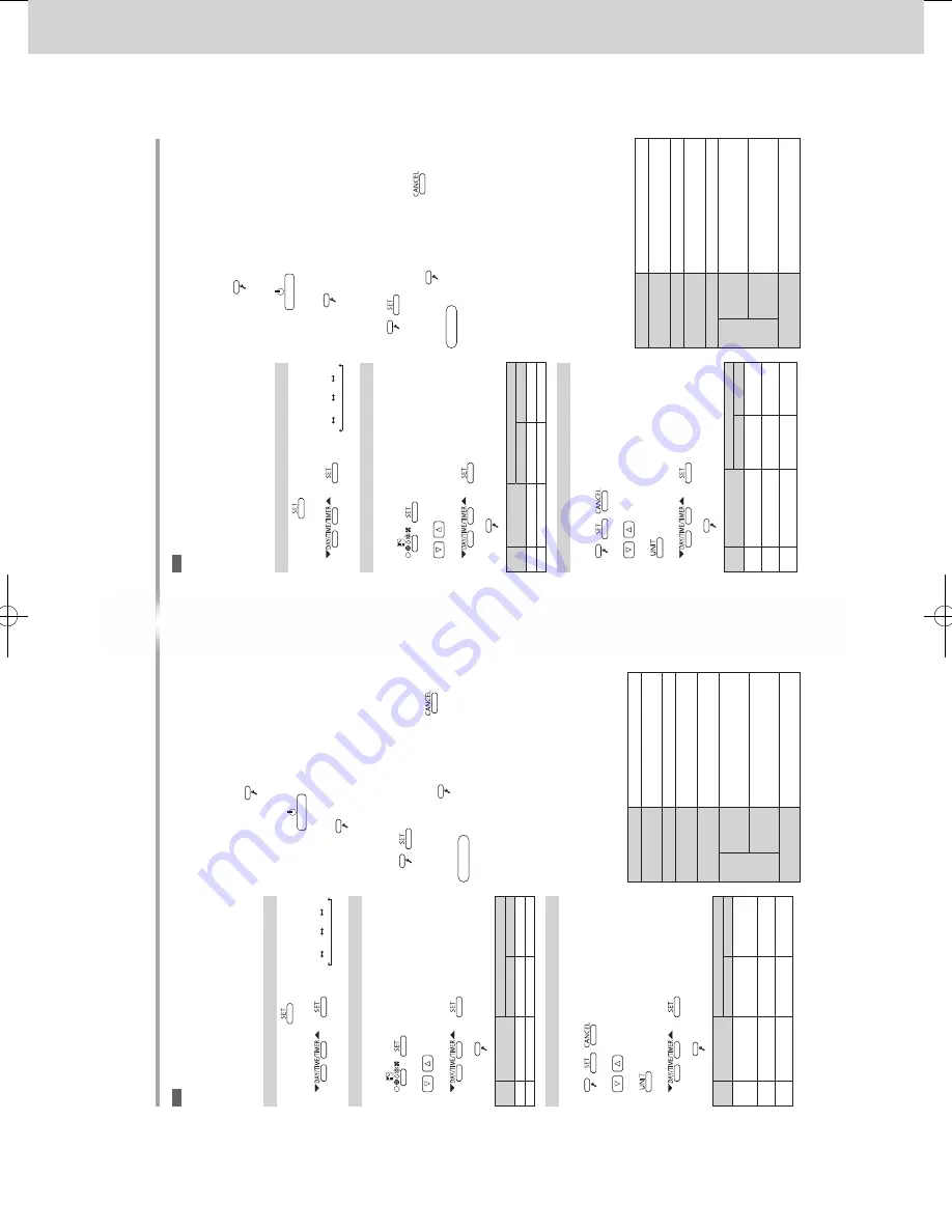
Con
guração
Relógio (Clock)
Modo de con
g.
do TC
(Principal/Secundário, T
ipo
de relógio)
Modo de con
guração detalhada (Con
guração
da
saída de ventilação, Sensor de temperatura da sala, Con
guração da apresentação da temperatura)
Relógio (Clock)
1
Mantenha
premido durante alguns segundos.
2
Con
gure o dia da semana, a hora e os minutos.
→
“
▼
”: Su
Mo
…
Sa
(Repita)
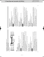
Modo de con
g. do TC (RC. setting mode)
1
Mantenha os 2 botões premidos aomesmo tempo durante alguns segundos.
A
,
2
Selecione o N.º de código.
3
Selecione os Dados de con
g.
→
O indicador acende depois de estar intermitente.
Prima
.
N.º de código
Item
Dados de con
g.
0000
0001
01
Pr
in
cip
al
/S
ec
un
dá
rio
Secundário
Principal
02
Tipo de relógio
24 horas
12 horas (AM/PM)
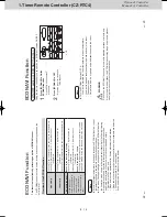
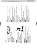
Modo de con
guração detalhada (Detailed setting mode)
1
Mantenha os 3 botões premidos aomesmo tempo durante alguns segundos.
,
,
2
Selecione o N.º de código.
3
Selecione o N.º da unidade.
4
Selecione os Dados de con
g.
→
O indicador acende depois de estar intermitente.
Prima
.
N.º de código
Item
Dados de con
g.
0000
0001
31
Con
guração
da
saída de ventilação
Não ligada
Ligada
32
Sensor de
temperatura da sala
Unidade principal
TC
33
Con
guração
da
apresentação da temperatura
°C
°F
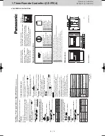
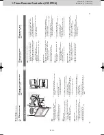
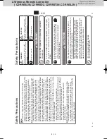
Teste de funcionamento
Ligue previamente o disjuntor
, consultando as instruções
de operação da unidade. O telecomando inicia.
1
Mantenha
premido durante alguns segundos.
Aparece a indicação [TEST]. (A
unidade entra no
modo de teste de funcionamento.)
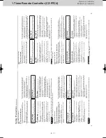
2
Prima
. Execute o teste de funcionamento.
A indicação [TEST] aparece durante o teste de funcionamento.
3
Prima
. T
ermine o teste de funcionamento.
A indicação [TEST] (T
este) desaparece.
4
Elimine o histórico de erros. Mantenha os 2 botões premidos aomesmo tempo durante alguns segundos.
,
São apresentadas informações relativas a erros.
Para eliminar o histórico de erros, prima
.
Prima o botão
para concluir o modo de manutenção.
Atenção
•
Não utilize este modo para outros
ns que não
o teste de funcionamento. (Para evitar uma sobrecarga das unidades)
•
Leia as instruções de instalação fornecidas com as
unidades.
•
As operações de
Aquecimento,
Arrefecimento
e V
entoinha podem ser executas apenas
individualmente.
•
A temperatura não pode ser alterada.
•
O modo de teste de funcionamento é desativado
automaticamente em 60 minutos. (Para evitar o contínuo funcionamento do teste)
•
As unidades exteriores não funcionam durante,
aproximadamente, 3 minutos depois de a alimentação ser ligada ou o funcionamento interrompido.
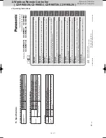
Especi
cações
N.º do modelo
CZ-R
TC4
Dimensões
(A)
120 mm × (L) 120 mm × (P) 20 + 4,75 mm
Peso
160
g
Intervalo da temperatura/humidade
0
C a 40
C / 20 % a 80 %
(sem condensação) *Apenas utilização interior
.
Fonte de alimentação
16 V CC (fornecida pela unidade interior)
Relógio
Precisão
± 30 segundos/mês (a uma temperatura normal de 25
C)
*Ajuste periodicamente.
Tempo de espera
24 horas (quando totalmente carregado) *São necessárias aproximadamente 8 horas para carregamento total.
Número de unidades interiores ligadas
Até 8 unidades
P
T
Con
guração / T
este de funcionamento / Especi
cações
業務用リモコン̲CZ-RTC4据付書.indd 23
2015/01/15 18:24:31
22
Setting / T
est operation / Speci
cations
(Continued)
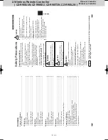
Impostazione
Orologio
Modal. telecomando (Princ/second.,
Tipo orologio)
Modalità Impost. dettagliate (Impostazione uscita ventola di ventilazione, Sensore della temperatura ambiente, Impostazione display temperatura)
Orologio
1
Tenere premuto
per diversi secondi.
2
Impostare il giorno della settimana, l’ora e i minuti.
→
“
▼
”: Su
Mo
…
Sa
(Ripetere)
Modal. telecomando
1
Tenere premuti i 2 pulsanti simultaneamente per diversi secondi.
A
,
2
Selezionare il Codice n.
3
Selezionare Imposta dati.
→
L’indicatore si illumina dopo aver lampeggiato.
Premere
.
Codice
n.
Voce
Imposta dati
0000
0001
01
Princ/second.
Second.
Principale
02
Tipo orologio
24 ore
12 ore (AM/PM)
Modalità Impost. dettagliate
1
Tenere premuti i 3 pulsanti simultaneamente per diversi secondi.
,
,
2
Selezionare il Codice n.
3
Selezionare il n. unità.
4
Selezionare Imposta dati.
→
L’indicatore si illumina dopo aver lampeggiato.
Premere
.
Codice
n.
Voce
Imposta dati
0000
0001
31
Impostazione uscita ventola di ventilazione
Non connesso
Connesso
32
Sensore della
temperatura ambiente
Unità principale
RC
33
Impostazione
display temperatura
°C
°F
Funzionamento di prova
Per prima cosa accendere l’interruttore circuito consultando le istruzioni per l’uso dell’unità. Dopo che il telecomando si è avviato.
1
Tenere premuto
per diversi secondi.
Viene visualizzato il display [TEST]. (L
’unità entra
in modalità funzionamento di prova.)
2
Premere
. Effettuare il funzionamento
di prova.
[TEST] viene visualizzato durante l’esecuzione del test.
3
Premere
. T
erminare il funzionamento di prova.
Scompare il display [TEST].
4
Cancellare la cronologia errori. Tenere premuti i 2 pulsanti simultaneamente per diversi secondi.
,
Vengono visualizzate le informazioni di errori.
Per cancellare la cronologia errori, premere
.
Premere il pulsante
per
nire la modalità di servizio.
Attenzione
•
Non utilizzare questa modalità per scopi diversi
dal funzionamento di prova. (Per prevenire il sovraccarico dell’unità)
•
Leggere le istruzioni per l’installazione in dotazione
alle unità.
•
Può essere ef
fettuata una qualsiasi delle operazioni
Caldo, Freddo e V
ent.
•
La temperatura non può essere modi
cata.
•
La modalità funzionamento di prova termina
automaticamente in 60 minuti. (Per prevenire la continuazione del funzionamento di prova)
•
Le unità esterne non operano per circa 3 minuti
dopo l’accensione o il termine del funzionamento.
Speci
che
Modello N.
CZ-R
TC4
Dimensioni
(H)
120 mm × (W) 120 mm × (D) 20 + 4,75 mm
Peso
160
g
Intervallo temperatura/umidità
Da 0 °C a 40 °C / dav 20 % a 80 % (Niente condensa) *Solo uso interno.
Fonte di Alimentazione
DC16 V (fornita dall'unità interna)
Orologio
Precisione
± 30 secondi/mese (alla temperatura normale di 25 °C) *Regolare periodicamente.
Tempo di tenuta
24 ore (se completamente carico) *Circa 8 ore sono necessarie per la ricarica completa.
Numero di unità interne connesse
Fino a 8 unità
I T
Impostazione / Funzionamento di prova / Speci
che
業務用リモコン̲CZ-RTC4据付書.indd 22
2015/01/15 18:24:29
SM830241-00_2WAY SYS.indb 26
2015/03/26 14:55:06
Summary of Contents for CZ-CSRC3
Page 18: ... MEMO 1 16 ...
Page 68: ...201504 ...


