


Optional Controller
Manual of Controller
Optional Controller
Manual of Controller
2
- 46
2. Wireless Remote Controller
( CZ-RWSU2N, CZ-RWSD2, CZ-RWST3N, CZ-RWSL2N )
15
Common to All Models
ENGLISH
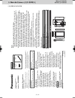
5-5.
R
oom
Temper
atur
e Sensor Settings
The indoor unit and the wir
eless r
emote contr
oller ar
e equipped with
room temper
atur
e sensors
. The sensing of r
oom temper
atur
e w
ork
s
via one of them.
When the unit is shipped, it is set to the indoor unit.
To s
witch it to the
remote contr
oller
, pr
ess the sensor button (the figur
e on the right)
inside the r
emote contr
oller’
s co
ver and then check that Main Sensor
on the L
CD scr
een goes off.
<Note>
Be sur
e to install the r
emote contr
oller so as to f
ace the
receiv
er
.
If the unit does not r
eceiv
e an
y r
oom temper
atur
e data fr
om
the r
emote contr
oller f
or ten minutes e
ven with its sensing
function activ
ated, the indoor unit sensor will automatically
star
t sensing the r
oom temper
atur
e.
Sensor button
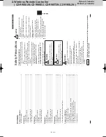
5-4.
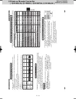
Self-diagnostics table and detected contents
The
“Alarm Displa
y”
sho
wn in the table belo
w e
xpr
esses the alarm contents displa
yed when the
wir
ed r
emote contr
oller is connected.
F
or ho
w to handle the alarms
, see installation instructions
of indoor units or technical guide
.
Detected contents
Indication lamp on the r
eceiv
er
Alarm Displa
y
O
P
ERA
TION
TIMER
ST
ANDB
Y
Blinking
Communication err
or in the r
emote
contr
oller cir
cuit
E01–E03, E08–E14, E17, E18
◎
Communication err
or either in the in/
outdoor oper
ation line or the sub-bus of
the outdoor unit
E04–E07, E15, E16, E19–E31
◎
Oper
ation of indoor pr
otection de
vice
P01, P09–P14
◎◎
Alternately
Oper
ation of outdoor pr
otection de
vice
P02–P08, P15–P31
◎
◎
Alternately
Err
or in the indoor thermistor
F01–F03, F10–F11
◎◎
Alternately
Err
or in the outdoor thermistor
F04–F09, F12–F28
◎◎
Alternately
Err
or in the indoor EEPR
OM
F29
◎◎
Simultaneously
Err
or in the outdoor EEPR
OM
F30, F31
◎◎
Simultaneously
Err
or r
elated to the compr
essor
H01–H31
◎
Err
or in indoor settings
L01–L03, L05–L09
◎
◎
Simultaneously
Err
or in outdoor settings
L04, L10–L31
◎
◎
Simultaneously
Err
or in the gas heat pump air
conditioner
A01–A31
◎◎
Simultaneously
Inconsistency in Cooling/Heating (Including an auto-temp setting f
or a model without auto-temp settings)
◎◎
Alternately
Oil alarm (Same as oper
ation of outdoor pr
otection de
vice)
◎
◎
Alternately
Test oper
ation
◎
◎◎
Simultaneously
: OFF
: ON (Illuminated)
◎
: Blinking (0.5 seconds inter
val)
270059_all.indb 15
2015-1-20 9:53:50
14
Common to All Models
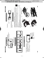
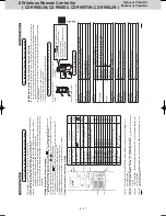
Pr
epar
ation
:
Turn on the cir
cuit br
eak
er of units and then turn the po
wer on.
After the po
wer is turned
on, r
emote contr
oller oper
ation is ignor
ed f
or appr
ox.
1 minute because setting is being
made
. This is not mal
funct
ion.
(Contents r
eceiv
ed while setting ar
e disabled.)
1.
T
o star
t test oper
ation, pr
ess and hold the emer
gency oper
ation button f
or 10 seconds
.
2.
The indication lamps (OPERA
TION,
TIMER, S
TANDB
Y) blink during test oper
ation.
3.
T
o finish test oper
ation, pr
ess and hold the emer
gency oper
ation button f
or 10 seconds
.
Attention
Do not use this mode f
or purposes other than
the test oper
ation.
(T
o pr
ev
ent o
verload of the units)
Read the installation instruct
ions supplied with the units
.
An
y of the Heat, Cool and F
an oper
ations can
only be per
formed.
Temper
atur
e cannot be changed.
The test oper
ation mode is automatically
turned off in 60 minutes
.
(T
o pr
ev
ent continuous test oper
ation)
Outdoor units do not oper
ate f
or appr
ox.
3
minutes after the po
wer is turned on or
oper
ation is stopped.
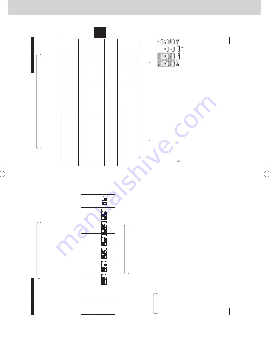
5-3.
Test
Oper
ation
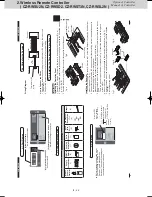
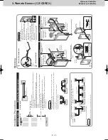
When mor
e than 1 r
eceiv
er is installed in the same r
oom, setting addr
esses pr
ev
ents
inter
fer
ence
.
F
or ho
w to change addr
esses of wir
eless r
emote contr
ollers
, see the oper
ating instruct
ions of
wir
eless r
emote contr
ollers
.
(C
Z-R
W
SU2N, C
Z-R
W
ST3N, C
Z-R
W
SD2)
T
o change the r
eceiv
er’
s addr
ess
, r
emo
ve the co
ver fr
om the r
eceiv
er’
s PCB and set No
.1 to
No
.3 of the [003] DIP s
witch on PCB
.
(C
Z-R
W
SL2N)
T
o change the r
eceiv
er’
s addr
ess
, set No
.1 to No
.3 of the [003] DIP s
witch on PCB on the
contr
ol panel.
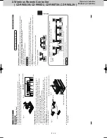
Remote Contr
oller
Addr
ess
Displa
y
Addr
ess
Addr
ess A
ddr
ess A
ddr
ess A
ddr
ess A
ddr
ess A
ddr
ess
ON/OFF
States
AL
L
123456
Position of the receiv
er’
s
addr
ess
switch
Receipt is possible at all of the addr
ess
positions
123
4
123
4
123
4
123
4
123
4
123
4
OFF
ON
5-2.
Setting A
ddr
ess S
witches
270059_all.indb 14
2015-1-20 9:53:49
SM830241-00_2WAY SYS.indb 46
2015/03/26 14:55:22
Summary of Contents for CZ-CSRC3
Page 18: ... MEMO 1 16 ...
Page 68: ...201504 ...


