EN
9
CZ-RWSL2
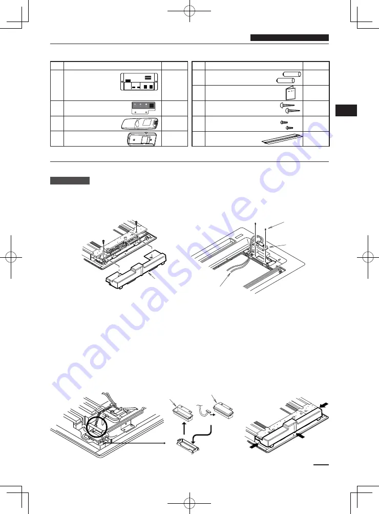
Accessories
No.
Accessories
Quantity
1
Operation Panel
1
2
Display
1
3
Remote Control
1
4
Remote Control Holder
1
No.
Accessories
Quantity
4
Dry-cell Batteries
2
5
Users Manual
1
6
Truss Self-Tapping Screws
4 × 16
2
7
Pan Head Self-Tapping Screws
4 × 10
4
8
Plastic Clamp L150
3
Installing the Display/Operation Panel
Resin Panel
Installing the Operation Panel
1 Remove the 2 screws and remove cover A from the back of the panel. (Fig. A)
2 Fasten the operation panel to the location in the diagram below with the 2 enclosed screws (4 × 10). (Fig. B)
3 Pass the wiring for the display (W2, 6P white connector) through the back of the panel.
Installing the Display
1 Cover B is fi tted inside cover A, so remove the 1 screw and detach it by pressing on it from the front side of the
panel. (Fig. C)
2 Connect the wiring (W2) for the display that is sticking out from the operation panel and fi t the display into the
panel.
Make sure the 6P white connector is fi rmly connected all the way in.
3 Bend the lead wire of the display into shape so it does not come in contact with the louver shaft.
There is a groove in the circled part in diagram 3 that is for passing wire through; press the lead wire into this
groove so there is no slack in it.
4 Attach cover A. When doing so, press it securely into the place indicated by the arrow in Fig D.
5 Shape the lead wire of the operation panel appropriately and fasten it with the enclosed plastic clamp.
6 Install the ceiling panel.
Fig. A
Cover A
Fig. B
Enclosed screws
(4 × 10)
Operation Panel
Display wiring (W2)
Fig. C
Fig. D
Cover B
Connect
Display


