Installation
2-2
Issued April 2000
Installation
The following procedure describes the hardware
setup required for Caller ID.
1. Remove the cover from the L-TRK card (VB-
43511A).
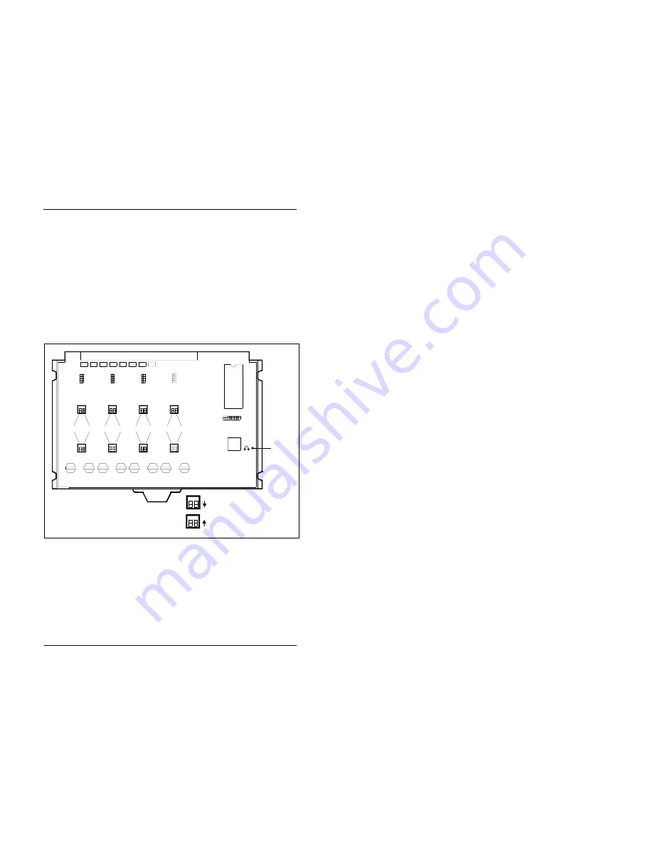
2. Cut strap J1 on the L-TRK card.
Figure 2-1. L-TRK Card Strap J1 and Switch Locations
ON
ON
ON
ON
ON
ON
ON
ON
ON
ON
L-TRK Card
(VB-43511A)
SW1
SW3
SW5
SW2
SW4
SW6
SW8
SW7
TK1
TK2
TK3
TK4
TK5
TK6
TK7
TK8
When a Caller ID Card Is Installed,
Set All Switches to the
OFF
Position
When No Caller ID Card Is Installed,
Set All Switches to the
ON
Position
J1
Strap J1
must be
cut to
receive
Caller ID


