background image

Appendix

Technical Information

E

NGLISH - 48

Q

Side by Side function signal combination table

Q

Movie signals

525i, 625i, 525p, 625p, 1 080/60i, 1 080/50i, 1 080/60p, 1 080/50p, 720/60p, 720/60p, NTSC, PAL and. 
SECAM.

1. Press the 

MENU

 button to display the password asking screen.

2. Press the 

AUTO SETUP

 button for more than 2 seconds.

3.

G

 for more than 2 seconds.

4. Press the 

MENU

 to display the password asking screen.

5. Enter the factory default password, “AAAA”, by pressing 

F


G


I


H

.

6. Select 

OK

 and press the 

ENTER

 button.

SIDE BY SIDE function signal combination table

Main image

Sub image

RGB1

RGB2

VIDEO

S-VIDEO

DVI-D

SDI

*1

Still

Movie

Still

Movie

Still

Movie

RGB1

Still

N/A

N/A

OK

OK

OK

OK

OK

OK

OK

Movie

N/A

N/A

OK

N/A

N/A

N/A

OK

N/A

N/A

RGB2

Still

OK

OK

N/A

N/A

OK

OK

OK

OK

OK

Movie

OK

N/A

N/A

N/A

N/A

N/A

OK

N/A

N/A

VIDEO

OK

N/A

OK

N/A

N/A

N/A

OK

N/A

N/A

S-VIDEO

OK

N/A

OK

N/A

N/A

N/A

OK

N/A

N/A

DVI-D

Still

OK

OK

OK

OK

OK

OK

N/A

N/A

N/A

Movie

OK

N/A

OK

N/A

N/A

N/A

N/A

N/A

N/A

SDI

*1

*1. PT-DZ6710E only.

OK

N/A

OK

N/A

N/A

N/A

N/A

N/A

N/A

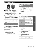
Restoring the MENU LOCK PASSWORD to default

Summary of Contents for DLP PT-D6000

Page 1: ...ns DLP Based Projector Model No PT DZ6710 PT DZ6700 PT DW6300 PT D6000 The information of these instructions are shared use with multiple models of DZ6710 series DZ6700 series DW6300 series and D6000 series TQBJ0299 Commercial Use ...

Page 2: ...MODE 25 SCREEN SETTING 25 AUTO SIGNAL 25 AUTO SETUP 26 DVI D IN 26 SDI IN 26 ON SCREEN DISPLAY 26 BACK COLOR 27 STARTUP LOGO 27 FREEZE 27 SIDE BY SIDE 27 PROJECTOR SETUP menu 28 PROJECTOR ID 28 INSTALLATION 28 HIGH ALTITUDE MODE 28 COOLING CONDITION 28 LAMP SELECT 29 LAMP RELAY 29 LAMP POWER 29 STANDBY MODE 29 RS 232C 29 REMOTE2 MODE 29 STATUS 30 FILTER COUNTER RESET 30 NO SIGNAL SHUT OFF 30 FUNCT...

Page 3: ...of the projected image SD Diagonal length of the projection area NOTE All following measurements and the calculation results are approximate and may differ slightly from the actual measurements The throw ratio is based on the value during projection onto an 80 inch screen size Lens shift is not available when using the ET DLE055 and so the height position H is SH 2 See the operating instructions t...

Page 4: ...8 077 12 923 23 63 31 66 17 11 24 70 29 89 47 26 47 11 71 26 71 22 112 77 0 4 04 26 5 42 4 77 6 103 10 56 1 81 98 155 154 6 233 9 233 7 369 11 0 13 3 Lens type Standard zoom lens Optional lens Height Lens names ET DLE055 ET DLE150 ET DLE250 ET DLE350 ET DLE450 Through ratio 1 8 2 4 1 0 8 1 1 3 1 9 1 2 3 3 6 1 3 6 5 4 1 5 5 8 6 1 SD SH SW LW LT Fixed LW LT LW LT LW LT LW LT H 50 0 623 1 107 1 96 2 ...

Page 5: ...17 96 25 94 31 39 49 62 49 47 74 82 74 8 118 43 0 81 4 04 26 5 42 4 78 102 11 58 11 85 1 102 11 162 9 162 3 245 5 245 4 388 6 2 7 13 3 Lens type Standard zoom lens Optional lens Height Lens names ET DLE055 ET DLE150 ET DLE250 ET DLE350 ET DLE450 Through ratio 1 8 2 4 1 0 8 1 1 4 2 0 1 2 4 3 8 1 3 8 5 7 1 5 6 9 0 1 SD SH SW LW LT Fixed LW LT LW LT LW LT LW LT H 50 0 623 1 107 1 98 2 63 0 9 1 49 2 1...

Page 6: ...6 19 46 05 69 65 69 61 110 23 0 4 57 30 40 72 7 95 10 54 10 79 2 95 10 151 6 151 228 6 228 4 361 7 0 14 11 Lens type Standard zoom lens Optional lens Height Lens names ET DLE055 ET DLE150 ET DLE250 ET DLE350 ET DLE450 Through ratio 1 8 2 4 1 0 8 1 1 3 2 0 1 2 4 3 7 1 3 7 5 6 1 5 6 8 9 1 SD SH SW LW LT Fixed LW LT LW LT LW LT LW LT H 50 0 623 1 107 1 95 2 6 0 89 1 47 2 15 2 58 4 12 4 06 6 2 6 05 9 ...

Page 7: ...89 x SD 0 0476 ET DLE150 Wide angle zoom lens 1 3 1 8 1 16 10 LW 0 0300 x SD 0 0540 LT 0 0433 x SD 0 0498 16 9 LW 0 0309 x SD 0 0540 LT 0 0445 x SD 0 0498 ET DLE250 Intermediate focus zoom lens 2 4 4 0 1 16 10 LW 0 0524 x SD 0 0800 LT 0 0828 x SD 0 0792 16 9 LW 0 0539 x SD 0 0800 LT 0 0851 x SD 0 0792 ET DLE350 Long focus zoom lens 3 8 6 0 1 16 10 LW 0 0827 x SD 0 1351 LT 0 1249 x SD 0 1346 16 9 L...

Page 8: ...40 40 40 HORIZONTAL KEYSTONE Correction angle β 15 15 15 15 15 15 Keystone and arc correction VERTICAL KEYSTONE Correction angle α 5 5 5 5 10 10 HORIZONTAL KEYSTONE Correction angle β 5 5 5 5 10 15 R2 L2 minimum value 1 2 3 1 6 1 2 0 8 0 6 R3 L3 minimum value 2 4 6 3 2 2 4 1 6 1 Arc correction R2 L2 minimum value 0 6 1 5 0 8 0 6 0 4 0 3 R3 L3 minimum value 1 2 4 3 1 6 1 2 0 8 0 5 NOTE When using g...

Page 9: ...rs to control the angle of the projector for adjusting the throwing angle Front leg adjusters and throwing angle NOTE Heated air comes out of the air exhaust port Do not touch the air exhaust port directly STANDBY RED STANDBY RED ON GREEN ON GREEN LAMP LAMP TEMP TEMP FILTER FILTER ...

Page 10: ...f equipment to the projector there is a possibility that the image will not be output correctly unless a compensator is used Before connection to the projector Pin assignments and signal names J S VIDEO IN J RGB2 IN Pin No Signal names Pin No Signal names 1 Ground luminance 1 R PR 2 Ground colour 2 G G SYNC Y 3 Luminance signal 3 B PB 4 Colour signal 12 DDC data 13 HD SYNC 14 VD 15 DDC clock J DVI...

Page 11: ...ected device See DVI D IN on page 26 Connecting example AV equipment NOTE When connecting with a VCR be sure to use the one with a built in time base corrector TBC or use a TBC between the projector and the VCR If non standard burst signals are connected the image may be distorted If this is the case connect a TBC between the projector and the VCR The DVI D signals input terminal supports only a s...

Page 12: ...PAL PAL M PAL N SECAM PAL60 RGB YCBCR VGA60 480p 480pRGB YPBPR 1080 60i 1035 60i 720 60p 1080 24p 1080 50i 1080 30p 1080 25p 1080 24sF 720 50p 480i 576i SHIFT page 18 ASPECT page 18 DEFAULT VID AUTO S1 AUTO VID AUTO PRI THROUGH 16 9 4 3 H FIT V FIT HV FIT ZOOM page 19 INTERNAL FULL CLOCK PHASE page 19 Default 16 GEOMETRY page 19 PT DZ6710E only OFF KEYSTONE CURVED PC GEOMETRY KEYSTONE VERTICAL KEY...

Page 13: ...JECTOR ID page 28 ALL 1 64 INSTALLATION page 28 FRONT FLOOR FRONT CEILING REAR FLOOR REAR CEILING HIGH ALTITUDE MODE page 28 OFF ON COOLING CONDITION page 28 FLOOR SETTING VERTICAL DOWN SETTING CEILING SETTING VERTICAL UP SETTING LAMP SELECT page 29 DUAL SINGLE LAMP1 LAMP2 LAMP RELAY page 29 OFF 00 00 23 00 LAMP POWER page 29 HIGH LOW STANDBY MODE page 29 NORMAL ECO RS 232C page 29 IN BAUDRATE IN ...

Page 14: ...CK page 36 OFF ON MENU LOCK PASSWORD page 36 CONTROL DEVICE SETUP page 36 CONTROL PANEL ENABLE DISABLE REMOTE CONTROLLER ENABLE DISABLE NETWORK SETUP page 37 HOST NAME DHCP IP ADDRESS SUBNET MASK DEFAULT GATEWAY STORE NETWORK CONTROL page 37 WEB CONTROL PJLink CONTROL COMMAND CONTROL COMMAND PORT STORE NETWORK STATUS page 37 DHCP IP ADDRESS SUBNET MASK DEFAULT GATEWAY DNS1 DNS2 MAC ADDRESS ...

Page 15: ... Called up item will be disappear after 5 seconds and return to the menu mode If there is a lower level the next level will be displayed You can reset some setting values to factory default by pressing the DEFAULT button 3 Press I H to adjust or set the selected item For items using a bar scale the current settings are displayed on the left of the bar scale You can cycle through the options of an ...

Page 16: ...s the ENTER button 2 Select WHITE BALANCE HIGH or WHITE BALANCE LOW and call up the scale bars by pressing I H or the ENTER button 3 Press I H to adjust the value of each colour Setting range WHITE BALANCE HIGH 0 to 255 Default 255 WHITE BALANCE LOW 0 to 63 Default 32 PICTURE MODE STANDARD Setting for a general image CINEMA Setting for a cinema type movie NATURAL Reproduces the original colour of ...

Page 17: ...l is changed the projector detects the colour system and selects the matched setting automatically or you can select manually Press I H to cycle through the options WHITE GAIN I More natural white H Whiter Setting range 0 to 10 SYSTEM DAYLIGHT VIEW OFF Deactive 1 Low 2 Middle 3 High SHARPNESS I Less sharp H More sharp Setting range 0 to 15 NOISE REDUCTION OFF Deactive 1 Low 2 Middle 3 High AI ON A...

Page 18: ... with S VIDEO and NTSC signals Q THROUGH The image will be displayed with the resolution of input signal Q 16 9 When a 16 10 16 9 or 15 9 signal is detected the image will be projected without any change and other signals will be adjusted to 16 9 Q 4 3 When a 4 3 or 5 4 signal is detected the image will be projected without any change and other signals will be adjusted to 4 3 with preserving origi...

Page 19: ... H HV FIT H VID AUTO Signals from other terminals VID AUTO H THROUGH H 16 9 H 4 3 H H FIT H V FIT H HV FIT H VID AUTO NOTE If you project an image with an unmatched aspect ratio the image may distort or some portions may be cropped Select an aspect ratio which preserves the intention of the image creator The order of ASPECT types is defined not only by the input method but also by the input signal...

Page 20: ...AL SUB KEYSTONE HORIZONTAL KEYSTONE HORIZONTAL SUB KEYSTONE LINEARITY LENS THROW RATIO Press I H to adjust throw ratio of the attached lens VERTICAL KEYSTONE HORIZONTAL KEYSTONE VERTICAL ARC HORIZONTAL ARC VERTICAL BALANCE HORIZONTAL BALANCE NOTE When GEOMETRY setting is set displayed menu or startup logo might be projected outside of the actual image area When GEOMETRY is selected EDGE BLENDING a...

Page 21: ... SUB KEYSTONE LINEARITY NOTE When KEYSTONE setting is set displayed menu or startup logo might be projected outside of the actual image area You can correct the distortion 30 degrees from the plane For a better quality image installing the projector with a minimum of distortion is recommended Some distortion may be retained for lens shift adjustment The result of the keystone correction will affec...

Page 22: ... NTSC 480i and 1080 60i input signals and change the setting properly OFF Deactive 25p FIXED Detects only PAL or SECAM 576i and 1080 50i signals and adjust the vertical resolution of the image to 2 2 pulldown 30p FIXED Detects only NTSC 480i and 1080 60i signals and adjust the vertical resolution of the image to 2 3 pulldown NOTE 25p FIXED or 30p FIXED setting with signals that is not 2 2 pulldown...

Page 23: ...ect MARKER and press I H to switch between ON OFF Green and red lines will be displayed Green line indicates START point and red line indicates WIDTH from START point Adjust START and WIDTH for superimposing the green line to the red Q Selecting gamma level You can adjust gamma level of the lapping area for fine adjustment 1 Select GAMMA and press the ENTER button 2 Press I H to cycle through the ...

Page 24: ...ITE only INTERLOCKED OFF Adjust RED GREEN and BLUE individually Setting range 0 to 255 OUTSIDE AREA If after the BRIGHT INSIDE adjustment only the vicinity of the borders of the areas where the pictures overlap and where the pictures do not overlap becomes bright proceed to adjust the width of connecting side Edge blending width right Projection range Bright adjustment right BRIGHT OUTSIDE BRIGHT ...

Page 25: ...DYNAMIC for using colorimeter NOTE If the TARGET DATA is outside the colour range of the projector the colours will not be projected correctly When each colour option is selected while AUTO TEST PATTERN is activated its one colour pattern will be displayed Adjusting red gain of red colour changes its luminance and likewise blue gain of blue and green gain of green COLOR MATCHING adjustment should ...

Page 26: ...ect the required MODE and change the DISPLAY DOTS value by pressing I H DVI D IN NOTE The DVI D IN setting for the best quality depends on the output equipment Refer the instructions of the connected equipment DVI signal is very sensitive and malfunction may occur or other problems could be encountered with some DVI equipment EDID3 Switch between fine settings for a moving image and for a still im...

Page 27: ...t OFF to escape from the SIDE BY SIDE mode To enter the SIDE BY SIDE mode again select SIDE BY SIDE of the menu BACK COLOR BLACK Displays black pattern BLUE Displays solid blue LOGO1 Displays user defined image LOGO2 Displays PANASONIC logo NOTE Special software is required to define the LOGO1 image Contact to an Authorised Service Centre STARTUP LOGO LOGO2 Displays PANASONIC logo NONE Deactive LO...

Page 28: ...ating instructions booklet that is provided with the projector INSTALLATION FRONT FLOOR Setting on a desk floor and projecting from front FRONT CEILING Mounting on the ceiling and projecting from front REAR FLOOR Setting on a desk floor and projecting from rear REAR CEILING Mounting on the ceiling and projecting from rear NOTE See Projection method in the operating instructions booklet that is pro...

Page 29: ...de The colours of the items indicate the status Green Current setting Yellow Current setting when a lamp fails or fails to light Red Lamp that has failed to light White Any other status If the projector is repeatedly used for short periods of time the lamps will need to be replaced more frequently LAMP RELAY OFF Deactive 00 00 23 00 1 hour interval from 00 00 to 23 00 NOTE Only when DUAL or SINGLE...

Page 30: ...lays type of projector SERIAL NUMBER Displays the serial number of the projector MAIN VERSION Displays the main version of the firmware of the projector unit SUB VERSION Displays the sub version of the firmware of the projector unit NETWORK VERSION Displays the network version of the projector unit ON COUNT POWER ON TIMES Displays the number of times the power has been tuned on LAMP1 ON Displays t...

Page 31: ...RITY PASSWORD on page 35 4 Press I to select OK then press the ENTER button When initialising by ALL USER DATA switch off the power and restart the projector SERVICE PASSWORD is for a service person Input the password with the numeric buttons of the remote control and press the ENTER button to confirm the entry DATE AND TIME TIME ZONE Select the current located time zone ADJUST CLOCK Adjust YEAR M...

Page 32: ...u 4 Press I H to select the required test pattern Press the ON SCREEN button to clear the screen if necessary TEST PATTERN Signal image FG FG Crosshatch All white FG FG Colour bars All black FG FG Window inversion Flag FG FG Window NOTE POSITION menu adjusting is not effective with the test patterns Remote control See Navigating through the menu on page 15 See Main menu and Sub menu on page 12 ...

Page 33: ...eleting a registered data You can delete a registered data from the REGISTERED SIGNAL LIST 1 Display the REGISTERED SIGNAL LIST and select the required signal data 2 Press the DEFAULT button Displays the REGISTERED SIGNAL STATUS of the signal for confirmation to delete 3 Press the ENTER button Displays REGISTERED SIGNAL LIST and confirm the data is deleted Press the MENU button to cancel and retur...

Page 34: ...R button Displays sub memory status and return to the projection MEMORY NO indicates as follows Q Displaying the sub memory list and restoring the settings 1 Press I or H while the menu is cleared from the screen after adjustment Displays the SUB MEMORY LIST 2 Select the required sub memory data and press the ENTER button Displays the REGISTERED SIGNAL STATUS 3 Press the ENTER button Restores the ...

Page 35: ...cted image while projecting You can enter your original text up to 22 characters for DISPLAY SETTING 1 Enter your original text Use F G I H to specify the location of the required character 2 Press the ENTER button The selected character will be displayed in the text box 3 Repeat until finish your original text Select or and press the ENTER button to move the cursor in the text box Select BS and p...

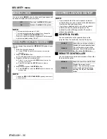
Page 36: ...OFF Deactivate the MENU LOCK system ON Activate the MENU LOCK system NOTE The factory default password is AAAA The factory default password is valid until you change the password in MENU LOCK PASSWORD menu When the projector is initialised the password will be changed to the factory default setting AAAA MENU LOCK PASSWORD NOTE Change the MENU LOCK PASSWORD regularly and make it uneasy to guess CON...

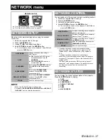
Page 37: ...ct SUBNET MASK numbers When DHCP is ON unnecessary to fill DEFAULT GATEWAY Enter correct DEFAULT GATEWAY numbers When DHCP is ON unnecessary to fill STORE Save the above settings NOTE Make sure the DHCP server is ready to use For details of IP ADDRESS SUBNET MASK and DEFAULT GATEWAY ask the network administrator Remote control See Navigating through the menu on page 15 See Main menu and Sub menu o...

Page 38: ...r should be Internet Explorer 6 0 or later To use the E mail function communication with E mail server must be established Make sure that E mail feature is available in your system Use a straight insulated LAN cable which supports category 5 or above The length of LAN cable must be 100 m or shorter LAN terminal NOTE If the LAN terminal is touched by electrostatically charged hands or body failure ...

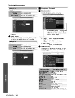
Page 39: ...ct Administrator to change and click NEXT 2 Enter User name and Password Accessing with the web browser NOTE Avoid activating two or more web browser simultaneously to work out setting or control actions Change the password first of all Administrator privileges enable the use of all functions User privileges enable the use of only Projector status Error information Network status Basic control and...

Page 40: ... new user name Password Enter new password Password Retype Enter the new password again User account New setting User name Enter new user name Password Enter new password Retype Enter the new password again Web browser buttons Remote control buttons 1 POWER ON STANDBY POWER ON and STANDBY SHUTTER ON OFF SHUTTER OSD ON OFF ON SCREEN RGB1 RGB2 DVI D VIDEO S VIDEO SDI RGB1 RGB2 DVI D VIDEO S VIDEO SD...

Page 41: ...te Enter the current date by YYYY MM DD then click Set date and time Time Enter the current time by hh mm ss then click Set date and time Web browser buttons Remote control buttons 1 Items Description Input IP address Enter the required IP address such as E mail server POP server or DNS server then click Submit to check whether the connection is functioned Connect success Connect failure Items Des...

Page 42: ...other mail for 60 minutes even the temperature of the projector is reached over the INPUT AIR TEMPERATURE setting INPUT AIR TEMPERATURE Modify the threshold temperature for sending temperature warning value control sends temperature warning mail Items Description E MAIL ADDRESS 1 E MAIL ADDRESS 2 E MAIL ADDRESS 1 E MAIL ADDRESS 2 Register the recipient E mail address Available to register up to 2 ...

Page 43: ...high such as near a heating appliance AROUND LAMP TEMPERATURE The temperature around the lamp is too high It may be that the projector s ventilation holes are blocked LAMP1 REMAIN TIME The lamp runtime has exceeded the prescribed cumulative time and it is now time to replace the lamp LAMP2 REMAIN TIME LAMP1 STATUS The lamp has failed to light Wait a short while for the lamp to cool off and then tu...

Page 44: ...in progress INPT Input selection 11 RGB1 21 VIDEO 31 DVI D 12 RGB2 22 S VIDEO 32 SDI PT DZ6710E only INPT Input selection query AVMT Shutter control 30 Shutter mode off picture mute cancelled 31 Shutter mode on picture mute AVMT Shutter mode query ERST Error status query 1st byte Indicates fan errors range 0 2 2nd byte Indicates lamp errors range 0 2 3rd byte Indicates Temperature errors range 0 2...

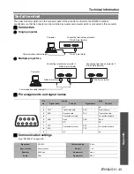
Page 45: ... 1 NC NC 2 TXD Transmitted data RXD Received data 3 RXD Received data TXD Transmitted data 4 Connected internally Connected internally 5 GND Earth GND Earth 6 NC NC 7 CTS Connected internally RTS Connected internally 8 RTS CTS 9 NC NC Computer Connecting terminals on projector D Sub 9 pin male Communication cable straight D Sub 9 pin female Computer Connecting terminals on projector 2 D Sub 9 pin ...

Page 46: ...r back only in the following cases If it coincides with the projector ID If the ID specification is ALL and responding ID ALL is on If the ID specification is Group and responding ID Group is on Command Control contents Parameter Remarks PON Power ON In standby mode all commands other than the PON command are ignored The PON command is ignored during lamp ON control POF Power OFF QPW Power query 0...

Page 47: ...wing buttons on the remote control and the operation area of the projector can no longer be operated when pins 1 and 9 are shortened POWER button and SHUTTER button Neither will it be possible to use the RS 232C commands or network functions corresponding to these functions If you short pin 1 and pin 9 and also short one of the pins from 3 to 7 and pin 1 then the following buttons on the projector...

Page 48: ...sword AAAA by pressing F G I H 6 Select OK and press the ENTER button SIDE BY SIDE function signal combination table Main image Sub image RGB1 RGB2 VIDEO S VIDEO DVI D SDI 1 Still Movie Still Movie Still Movie RGB1 Still N A N A OK OK OK OK OK OK OK Movie N A N A OK N A N A N A OK N A N A RGB2 Still OK OK N A N A OK OK OK OK OK Movie OK N A N A N A N A N A OK N A N A VIDEO OK N A OK N A N A N A OK...

Page 49: ...s Corporation S VGA is a registered trademark of the Video Electronics Standards Association The font used in the on screen displays is a Ricoh bitmap font which is manufactured and sold by Ricoh Company Ltd All other trademarks are the property of the various trademark owners Trademark acknowledgements ...

Page 50: ...NPUT GUIDE 26 INPUT RESOLUTION 22 INSTALLATION 28 K KEYSTONE 21 L LAMP POWER 29 LAMP RELAY 29 LAMP SELECT 29 LOAD ALL USERS DATA 31 M Menu Navigation 15 Structure 12 MENU LOCK 36 MENU LOCK PASSWORD 36 N NETWORK 37 Network Connection 38 Detailed set up 41 LAN terminal 38 Projector Control 40 NETWORK CONTROL 37 NETWORK SETUP 37 NETWORK STATUS 37 NO SIGNAL SHUT OFF 30 NOISE REDUCTION 17 O ON SCREEN D...

Page 51: ...al terminal 45 SERVICE PASSWORD 31 SHARPNESS 17 SHIFT 18 SIDE BY SIDE 27 Combination table 48 SIGNAL LIST 33 STANDBY MODE 29 STARTUP LOGO 27 STATUS 30 43 SUB MEMORY LIST 33 SYSTEM DAYLIGHT VIEW 17 SYSTEM SELECTOR 17 T TEST PATTERN 32 TEXT CHANGE 35 Throw distance 3 Throwing angle 9 TIME 31 TINT 16 W WARNING MESSAGE 26 WHITE GAIN 17 Z ZOOM 19 ...

Page 52: ...Printed in Japan S0209 1039B ...

Reviews: