53
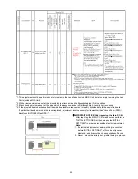
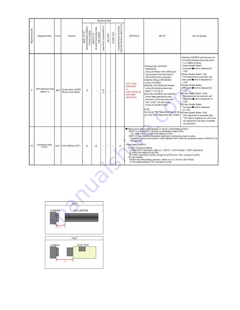
*1 :This adjustment must be performed not only replacing the Lens Parts (Include MOS Unit), but also simply removing the Lens
Parts (Include MOS Unit).
*2 :White missing pixels means that the pixel which is always active (lit) although shading (Dark) condition.
*3 :Black missing pixels means that the pixel which is always non-active (off) although high-intensity light is coming.
*4 :If the adjusted data is backed up from the main board before replacement or repair, write the data to the new main board.
If parts other than the main board are not replaced, adjustment is not necessary for items other than "Venus Zoom (PZM)/
Backfocus/GYRO(BF)/Flash(STB)".
Q
IMPORTANT NOTICE (After replacing the Main P.C.B.)
After replacing the MAIN P.C.B., make sure to perform the
"INITIAL SETTINGS" first, then release the "INITIAL
SETTINGS" in order to proceed the electrical adjustment.
Note:
1. If electrical adjustment or data re-writing is executed
before "INITIAL SETTINGS", suffix code list is never
displayed, and it cannot be chosen suitable suffix code.
2. Never remove the battery during initial setting in process.
Summary of Contents for DMC-FT5EA
Page 36: ...36 9 Disassembly and Assembly Instructions 9 1 Disassembly Flow Chart 9 2 P C B Location ...
Page 38: ...38 9 3 2 Removal of Rear Aluminum Case Unit Fig D2 9 3 3 Removal of Rear Case Unit Fig D3 ...
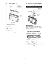
Page 44: ...44 9 3 8 Removal of Top FPC Unit Fig D14 9 3 9 Removal of Speaker Fig D15 ...
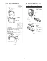
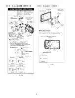
Page 46: ...46 9 3 12 Removal of MIC G FPC P C B Fig D18 9 3 13 Removal of LCD Unit Fig D19 ...
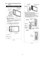
Page 47: ...47 9 3 14 Removal of Rear Operation FPC P C B Fig D20 Fig D21 ...
Page 56: ...56 ...


