8
3 Service Navigation
3.1.
Introduction
This service manual contains technical information, which will allow service personnel's to understand and service this model.
Please place orders using the parts list and not the drawing reference numbers.
If the circuit is changed or modified, the information will be followed by service manual to be controlled with original service manual.
3.2.
Service Navigation
3.2.1.
About lens block
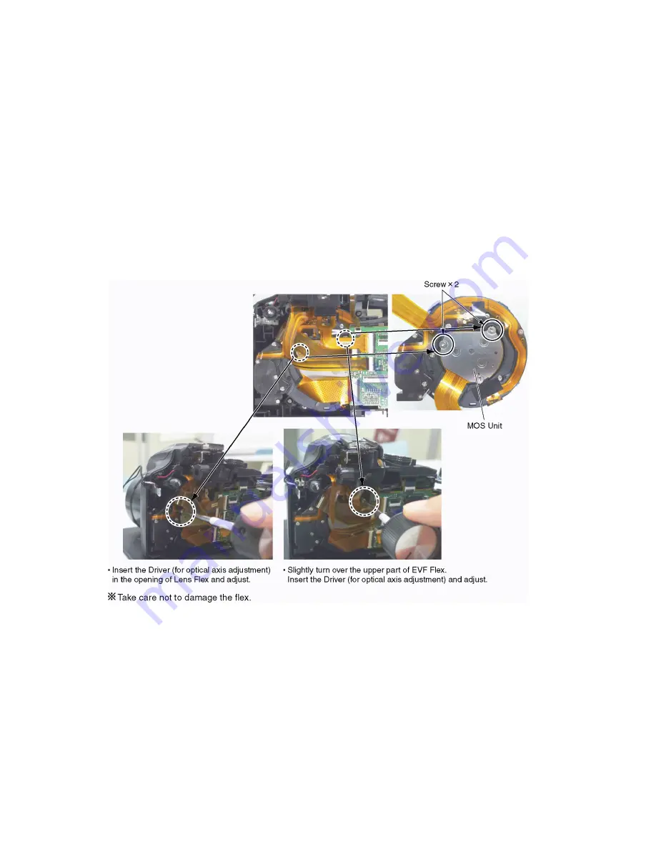
The image sensor (MOS) unit which are connected to the lens unit with 3 screws. 2 of these 3 screws are locked, after performing
the Optical tilt adjustment. During servicing, if one of MOS fixing screws are loosened, the Optical tilt adjustment must be
performed. (About the Optical tilt adjustment, refer to the "9.3.2 Adjustment Specifications" for details.)
The Optical tilt adjustment can be performed with the Rear Case opened.
NOTE:
It is necessary to use the "DSC_Tilt" software to allow the "Optical tilt adjustment".
The Adjustment software "DSC_Tilt" is available at "TSN Website".
Summary of Contents for DMC-FZ70GC
Page 21: ...21 8 Disassembly and Assembly Instructions 8 1 Disassembly Flow Chart 8 2 P C B Location ...
Page 23: ...23 Fig D2 8 3 2 Removal of the Main P C B Fig D3 Fig D4 ...
Page 25: ...25 8 3 5 Removal of the Lens Unit Fig D7 8 3 6 Removal of the LCD Unit Fig D8 ...
Page 26: ...26 8 3 7 Removal of the Flash P C B Fig D9 Fig D10 ...
Page 28: ...28 Fig D13 Fig D14 ...


