S-5
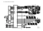
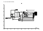
S2.4. SENSOR BLOCK DIAGRAM
IC3101
Q3101
IC3004
IC3002
SUBSW
(CCD IMAGE SENSOR)
VO
VH
16
23
24
20
21
18
(V-CCD DRIVER)
(CDS/AGC/AD/TG)
26
54
CDS
AGC
(PGA)
SERIAL
I/F
A/D
(12bit)
32
31
30
D0 39
OSUB
27
FP9005
22
FP9005
28
1
10
FP9005
27
FP9005
25
FP9005
24
FP9005
17
FP9005
8
FP9005
4
50
OV1B
SUB
37
HD
36
VD
34
FLASH
SCK SDATA
SL
D11
12bit
55
62
3
10
53 44 58 45
52 57 60 63
CH1
CH8
V1
V10
VSG1
VSG8
11
12
H1 H2
MSHUT
14
5
SUBCK
SUB
35
23
22
23
31
OV1A
OV3A
OV3B
OV3A
20 RG
AFE CS
AFE SDATA
AFE SCK
2176pix
3856pix
3860pix
xi
p0
81
2
2176
3856
2
2
50
2
12
6
10
2
OB
CCD Image Sensor (Unit: pixels)
: OB AREA
: TRANJENT AREA
: EFFECTIVE AREA
FP9005
23
22
21
OV4
20
OV5A
61 46
51
VB
V6
H1
H2
HL
RG
FP9005
9
FP9005
10
FP9005
11
FP9005
14
FP9005
15
FP9005
16
9
V2
6
V3A
5
V3B
4
V4
3
V5A
2
V5B
CL3013
CL3012
RL3009
RL3008
RL3007
FLASH TRG
CCDVD
CCDHD
CCD IN
X3001
(36.0MHz)
CLI 24
CLO 23
1 2
33
4
SUBCNT
3
55
26
30
OV5B
OV5R
VH
Q3102
FP9005
7
11
V1A
8
7
FP9005
12
FP9005
13
FP9005
18
FP9005
19
25
V7R
26
28
19
15
OV2
OV6
OV7A
OV7B
30
09
L
C
40
09
L
C
50
09
L
C
60
09
L
C
70
09
L
C
80
09
L
C
90
09
L
C
01
09
L
C
10
9L
C
1
21
09
L
C
31
09
L
C
41
09
L
C
51
09
L
C
17
HL
V1
V8
50 54
V5R
V7R
56 59 62
53 VSUB
25 OV7R
91
09
L
C
02
09
L
C
62
09
L
C
62
09
L
C
52
09
L
C
42
09
L
C
FP9005
20
25
V5R
61
09
L
C
V7A
V7B
V8
DMC-LX1
SENSOR BLOCK
DIAGRAM
Summary of Contents for DMCLX1PP - DIGITAL STILL CAMERA
Page 8: ...8 NOTE Above caution is applicable for a battery pack which is for DMC LX1 series as well ...
Page 12: ...12 4 Specifications ...
Page 13: ...13 5 Location of Controls and Components ...
Page 14: ...14 ...
Page 15: ...15 ...
Page 22: ...22 8 Disassembly and Assembly Instructions 8 1 Disassembly Flow Chart 8 2 PCB Location ...
Page 24: ...24 8 3 2 Removal of the LCD Unit Fig D2 8 3 3 Removal of the Top Operation Unit Fig D3 ...
Page 26: ...26 8 3 7 Removal of the Battery Case Fig D7 8 3 8 Removal of the Top Operation PCB Fig D8 ...
Page 27: ...27 Fig D9 8 3 9 Removal of the Flash Unit Fig D10 ...
Page 36: ......
Page 52: ...S 16 ...

