28
11 Disassembly and Assembly Instructions
11.1. Unit
11.1.1. Disassembly Flow Chart
The following chart is the procedure for disassembling the casing and inside parts for internal inspection when carrying out the ser-
vicing.
To assemble the unit, reverse the steps shown in the chart below.
11.1.2. P.C.B. Positions
Summary of Contents for DMP-BD77P
Page 5: ...5 2 2 Precaution of Laser Diode ...
Page 10: ...10 4 1 Others Licenses ...
Page 11: ...11 ...
Page 12: ...12 ...
Page 16: ...16 7 2 1 Open Mode Remote Cont Buttons OK Yellow Blue ...
Page 20: ...20 ...
Page 21: ...21 ...
Page 22: ...22 9 Troubleshooting Guide 9 1 About Operation of Set ...
Page 23: ...23 9 2 About Circuit ...
Page 24: ...24 ...
Page 25: ...25 ...
Page 26: ...26 ...
Page 27: ...27 10 Wiring Connection and Voltage Data ...
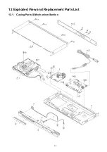
Page 33: ...33 12 Exploded View and Replacement Parts List 12 1 Casing Parts Mechanism Section ...


