30
11.1.5. SW P.C.B. and Wireless P.C.B.
1. Unlock 2 tabs (A) to remove the SW P.C.B..
2. [DMP-BD87 only]
Unlock tab (B) to remove the Wireless P.C.B..
11.1.6. Back Panel
1. Remove the 2 screws (A) and 1 screw (B).
2. Unlock 2 locking tabs (A) to remove the Back Panel.
11.1.7. Power Supply P.C.B.
1. Remove the connector (A), then remove AC cord.
2. Remove the 2 screws (A) and screw (B), then lift up
straight upward the Power Supply P.C.B. and disconnect
the connector (B) to remove the Power Supply P.C.B..
11.1.8. Digital P.C.B.
1. Remove the connector (A) and FFC (A).
2. Remove the screw (A), the lift up the Digital P.C.B.
3. Remove the FFC (B), and isolate it with an ESD preven-
tion bag (RPFC0114).
4. Remove the Digital P.C.B..
Summary of Contents for DMP-BD77P
Page 5: ...5 2 2 Precaution of Laser Diode ...
Page 10: ...10 4 1 Others Licenses ...
Page 11: ...11 ...
Page 12: ...12 ...
Page 16: ...16 7 2 1 Open Mode Remote Cont Buttons OK Yellow Blue ...
Page 20: ...20 ...
Page 21: ...21 ...
Page 22: ...22 9 Troubleshooting Guide 9 1 About Operation of Set ...
Page 23: ...23 9 2 About Circuit ...
Page 24: ...24 ...
Page 25: ...25 ...
Page 26: ...26 ...
Page 27: ...27 10 Wiring Connection and Voltage Data ...
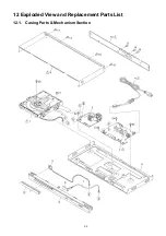
Page 33: ...33 12 Exploded View and Replacement Parts List 12 1 Casing Parts Mechanism Section ...


