background image

6

2.3.

Static Electricity Protection Measures

• The laser diode in the traverse unit (optical pick-up) may break down due to potential difference caused by static electricity of

clothes or human body.
So, be careful of electrostatic breakdown during repair of the traverse unit (optical pick-up).

2.4.

Ground for electrostatic breakdown prevention

• As for parts that use optical pick-up (laser diode), the optical pick-up is destroyed by the static electricity of the working environ-

ment.
Repair in the working environment that is grounded.

2.4.1.

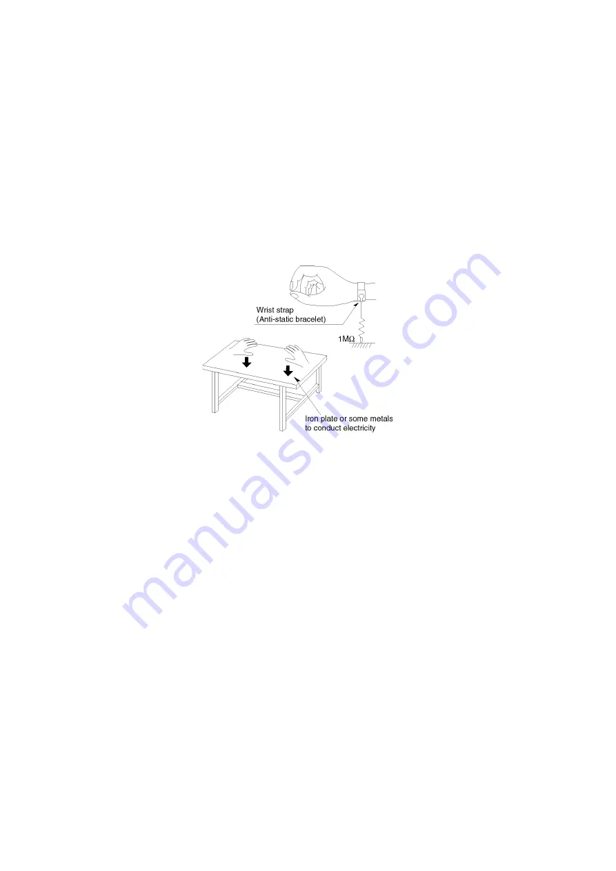
Work table grounding

• Put a conductive material (sheet) or steel sheet on the area where the traverse unit (optical pick-up) is placed, and ground the

sheet.

2.4.2.

Human body grounding

• Use the anti-static wrist strap to discharge the static electricity from your body.

2.4.3.

When exchange the Drive

• Before remove the ESD prevention bag, make sure to use the anti-static wrist strap to discharge the static electricity when

replace the Drive.

Note:

The ESD prevention bag is used to replace the original short-circuit point.
It can be removed while placing the Drive.

Summary of Contents for DMP-BD77P

Page 1: ...anasonic Corporation 2012 Unauthorized copy ing and distribution is a violation of law ORDER NO DSD1201001CE B24 Blu ray Disc Player Model No DMP BD87P DMP BD87PC DMP BD77P DMP BD77PC Colour K Black Type ...

Page 2: ...ctions 14 6 1 Taking out the Disc from Drive Unit when the Disc cannot be ejected by OPEN CLOSE button 14 7 Multiple Pressing Function 15 7 1 About the Multiple Pressing of the Unit s Remote Control 15 7 2 How to enter the Special Modes using the Multiple Pressing Function of the Unit s Remote Control 15 8 Service Mode 18 8 1 About the Service Mode 18 8 2 Service Mode List 19 9 Troubleshooting Gui...

Page 3: ...exposed to shock hazards 1 2 Leakage Current Cold Check 1 Unplug the AC cord and connect a jumper between the two prongs on the plug 2 Measure the resistance value with an ohmmeter between the jumpered AC plug and each exposed metal lic cabinet part on the equipment such as screwheads connectors control shafts etc When the exposed metal lic part has a return path to the chassis the reading should ...

Page 4: ... solder or unsolder ES devices 4 Use only an antistatic solder removal device Some solder removal devices not classified as antistatic ESD protected can generate electrical charge sufficient to damage ES devices 5 Do not use freon propelled chemicals These can generate electrical charges sufficient to damage ES devices 6 Do not remove a replacement ES device from its protective package until immed...

Page 5: ...5 2 2 Precaution of Laser Diode ...

Page 6: ...city of the working environ ment Repair in the working environment that is grounded 2 4 1 Work table grounding Put a conductive material sheet or steel sheet on the area where the traverse unit optical pick up is placed and ground the sheet 2 4 2 Human body grounding Use the anti static wrist strap to discharge the static electricity from your body 2 4 3 When exchange the Drive Before remove the E...

Page 7: ...The firmware of the unit may be renewed to improve the quality including operational performance and playability Make sure to refer the following procedure when performing version up 3 2 1 Confirmation of the Firmware Version Perform following steps to checking the firmware version currently installed in the unit 1 Turn the unit on and wait the Home screen is displayed 2 Select Setup Player Settin...

Page 8: ...re required for version up can be downloaded from Support Information from NWBG VDBG PAVC web site in TSN system Click file name to download After download click file to decompress Total 1 file 2 Decompress the downloaded file The decompressed file will be named as follows File Name PANA_DVD FRM Copy the file to root folder of the USB device If using CD R instead of USB device burn the file to a b...

Page 9: ...gion number 1 or ALL BD Video region code A Media Playable disc BD Video BD LIVE BD ROM Version 2 4 BD RE Version3 Single Layer Dual Layer JPEG BD R Version2 Single Layer Dual Layer MKV DVD R DVD R DL DVD Video format 1 DVD Video Recording format 1 AVCHD format 1 JPEG 2 FLAC MP3 MKV WAV DVD RW DVD Video format 1 DVD Video Recording format 1 AVCHD format 1 R RW R DL Video 1 AVCHD format 1 DVD Video...

Page 10: ...10 4 1 Others Licenses ...

Page 11: ...11 ...

Page 12: ...12 ...

Page 13: ... control signal 12 Open or close the disc tray 13 Show NETFLIX screen 14 Switch on off Secondary Video Picture in picture 15 Show Setup menu 16 Exit the menu screen 17 Show the selection screen of network features 18 Show HOME menu 19 Move the highlight for selection OK Confirm the selection Frame by frame 20 Return to previous screen 1 Standby on switch I Press to switch the unit from on to stand...

Page 14: ...orcible Disc Eject 6 1 2 When the Disc Eject can not be done 1 Turn off the power and pull out AC cord 2 Put the unit so that bottom can be seen 3 Insert paper clips etc into the hole on the bottom of Drive and slide the paper clips etc in the direction of the arrow to eject tray slightly 4 Pull the unit upward and pull out tray ...

Page 15: ...initial settings and the Service Mode etc The Multiple Pressing function is not available for conventional models remote control Use the remote control included this unit 7 2 How to enter the Special Modes using the Multiple Pressing Function of the Unit s Remote Control For pressing the multiple buttons of the remote control this unit can be entering each of the following special modes After ente...

Page 16: ...16 7 2 1 Open Mode Remote Cont Buttons OK Yellow Blue ...

Page 17: ...17 7 2 2 Privately Mode 1 Remote Cont Buttons 6 7 Yellow 7 2 3 Privately Mode 2 Remote Cont Buttons 5 9 Red ...

Page 18: ... Informations necessary for service can be displayed 8 1 1 How to enter the Service Mode 8 1 2 How to exit the Service Mode Press and hold the Power button remote control or unit The Service Mode is terminated and automatically turns the unit off ...

Page 19: ...19 8 2 Service Mode List The display of information to each command is as follows Note Do not use it excluding the designated command ...

Page 20: ...20 ...

Page 21: ...21 ...

Page 22: ...22 9 Troubleshooting Guide 9 1 About Operation of Set ...

Page 23: ...23 9 2 About Circuit ...

Page 24: ...24 ...

Page 25: ...25 ...

Page 26: ...26 ...

Page 27: ...27 10 Wiring Connection and Voltage Data ...

Page 28: ...11 1 1 Disassembly Flow Chart The following chart is the procedure for disassembling the casing and inside parts for internal inspection when carrying out the ser vicing To assemble the unit reverse the steps shown in the chart below 11 1 2 P C B Positions ...

Page 29: ... Panel 11 1 4 1 Tray Ornament 1 Insert paper clips etc into the hole on the bottom of BD Drive and slide the lever in the direction of arrow to eject tray slightly 2 Unlock 2 tabs turn Pull the Tray Ornament in direction of 2 11 1 4 2 Front Panel 1 Remove the connector A and B the connector B is installed DMP BD87 only 2 Unlock 5 tabs A E turn Pull with the Front Panel in the direction of your sid...

Page 30: ...ck Panel 11 1 7 Power Supply P C B 1 Remove the connector A then remove AC cord 2 Remove the 2 screws A and screw B then lift up straight upward the Power Supply P C B and disconnect the connector B to remove the Power Supply P C B 11 1 8 Digital P C B 1 Remove the connector A and FFC A 2 Remove the screw A the lift up the Digital P C B 3 Remove the FFC B and isolate it with an ESD preven tion bag...

Page 31: ...31 11 1 9 Mechanism Unit 1 Remove the 2 screws A then remove the Mechanism Unit When assembling first set the Mechanism unit to tabs A then tighten the 2 screws A ...

Page 32: ...ital P C B When replacing the mechanism unit Digital P C B or both the drive adjustment is required 11 2 1 List of Service Tools 11 2 1 1 Adjustment Inspection Tools 11 2 1 2 Commercial Tools Required 11 2 2 How to adjust the Mechanism Unit Digital P C B ...

Page 33: ...33 12 Exploded View and Replacement Parts List 12 1 Casing Parts Mechanism Section ...

Page 34: ...34 12 2 Packing Accessories Section ...

Page 35: ...WIRELESS P C B 1 BD87P PC 7 VEE1M14 WIRELESS P C B CABLE 1 BD87P PC 8 VGP6493 FRONT PANEL 1 BD87P PC 8 VGP6492 FRONT PANEL 1 BD77P PC 9 VGP6498 TOP PANEL 1 10 VGP6503 BACK PANEL 1 BD87P 10 VGP6506 BACK PANEL 1 BD87PC 10 VGP6502 BACK PANEL 1 BD77P 10 VGP6505 BACK PANEL 1 BD77PC 11 VKU0610 BOTTOM CABINET 1 12 RGK2378 K TRAY ORNAMENT 1 13 VHD2326 SCREW 1 14 VHD2326 SCREW 1 15 VHD2326 SCREW 1 16 VHD23...

Reviews: