34
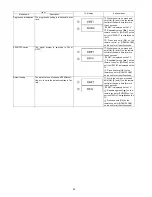
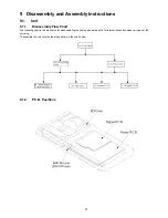
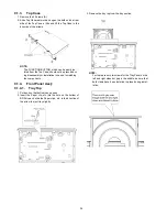
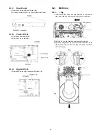
9.1.3.
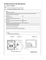
Top Case
1. Remove the 3 Screws (A).
2. Slide Top Case rearward and open the both ends at rear
side of the Top Case a little and lift the Top Case in the
direction of the arrows.
NOTE:
The FUNCTION BUTTON, which can be easily iso-
lated from the Top Case, should not be pressed dur-
ing disassembly or installation in case of scratching
the components.
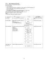
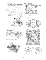
9.1.4.
Front Panel Ass'y
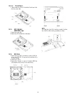
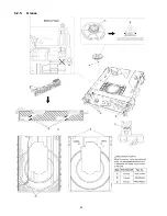
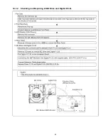
9.1.4.1.
Tray Top
1. Put deck so that bottom can be seen.
2. Insert the Paper clip, etc. into the hole on the bottom of
BD Drive and slide the Paper clips, etc. in the direction of
the arrow to eject tray slightly.
3. Remove the tray top from the tray section.
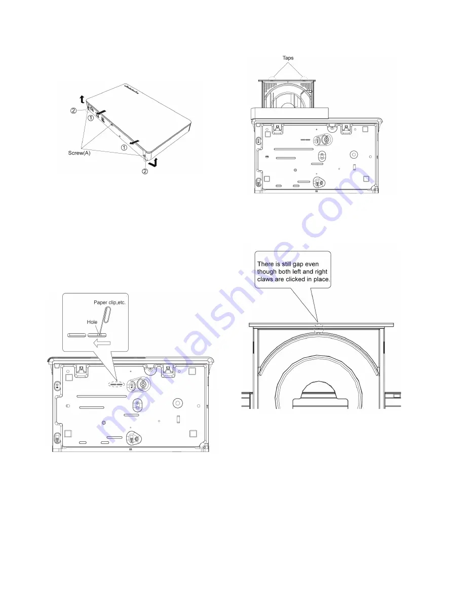
NOTE:
For there are only two claws for the Tray Panel on the
left and right sides but gap in the middle, be sure that
both claws have been installed in place during instal-
lation.
Summary of Contents for DMP-BD81PU
Page 2: ...2 ...
Page 3: ...3 ...
Page 8: ...8 2 2 Precaution of Laser Diode ...
Page 18: ...18 5 Location of Controls and Components ...
Page 40: ...40 9 2 5 Grease ...
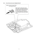
Page 44: ...44 9 3 3 How to Clean the Lens of Optical Pick UP ...
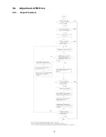
Page 45: ...45 9 4 Adjustment of BD Drive 9 4 1 Repair Flowchart ...
Page 49: ...49 10 1 2 Checking and Repairing of BD Drive and Digital P C B ...
Page 59: ...Model No DMP BD91GN 81PU 81GA 81GC 81GN 81GT BDT160GA 160GN 160GW BDT161GC PART LIST NOTICE ...
Page 60: ...Model No DMP BD91GN 81PU 81GA 81GC 81GN 81GT BDT160GA 160GN 160GW BDT161GC ABBREVIATION ...
Page 79: ...Model No DMP BD91GN 81PU 81GA 81GC 81GN 81GT BDT160GA 160GN 160GW BDT161GC Exploded View ...
Page 80: ...Model No DMP BD91GN 81PU 81GA 81GC 81GN 81GT BDT160GA 160GN 160GW BDT161GC Mechanism View ...
Page 81: ...Model No DMP BD91GN 81PU 81GA 81GC 81GN 81GT BDT160GA 160GN 160GW BDT161GC Packing View ...


