35
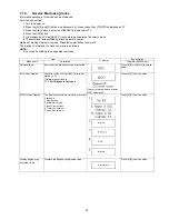
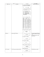
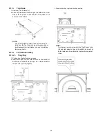
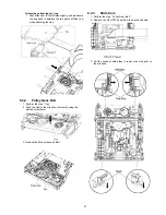
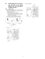
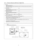
9.1.4.2.
Front Panel
1. Unlock 6 tabs (A)-(F) turn. Pull with the Front Panel in the
direction of your side.
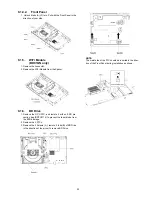
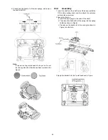
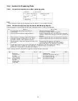
9.1.5.
WiFi Module
(BD91GN only)
1. Remove the connector.
2. Remove the WiFi Module from the Spacer.
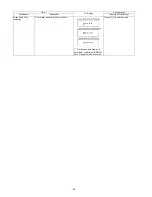
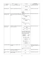
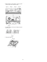
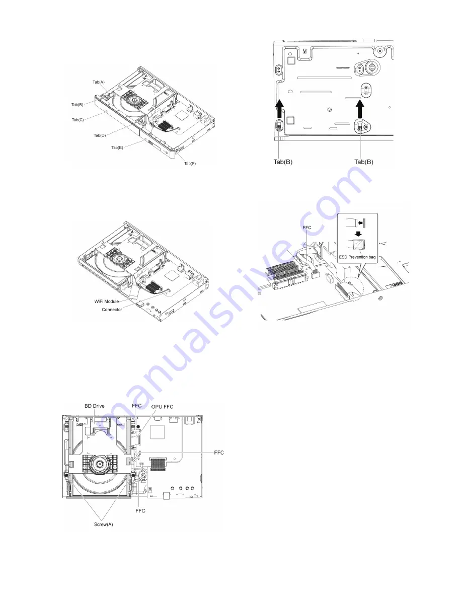
9.1.6.
BD Drive
1. Remove the OPU FFC, and isolate it with an ESD pre-
vention bag (RPFC0114) to prevent the laser diode from
the ESD damage.
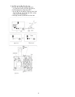
2. Remove the 3 FFCs.
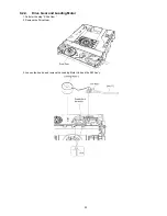
3. Remove the 2 Screws (A ), remove 2 tabs (B) of BD Drive
in the direction of the arrow, to remove BD Drive.
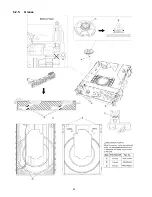
NOTE:
The metal side of the FFC should be inserted in the direc-
tion of the Front Panel during installation as shown.
Summary of Contents for DMP-BD81PU
Page 2: ...2 ...
Page 3: ...3 ...
Page 8: ...8 2 2 Precaution of Laser Diode ...
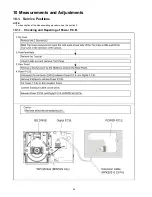
Page 18: ...18 5 Location of Controls and Components ...
Page 40: ...40 9 2 5 Grease ...
Page 44: ...44 9 3 3 How to Clean the Lens of Optical Pick UP ...
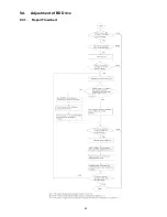
Page 45: ...45 9 4 Adjustment of BD Drive 9 4 1 Repair Flowchart ...
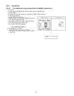
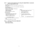
Page 49: ...49 10 1 2 Checking and Repairing of BD Drive and Digital P C B ...
Page 59: ...Model No DMP BD91GN 81PU 81GA 81GC 81GN 81GT BDT160GA 160GN 160GW BDT161GC PART LIST NOTICE ...
Page 60: ...Model No DMP BD91GN 81PU 81GA 81GC 81GN 81GT BDT160GA 160GN 160GW BDT161GC ABBREVIATION ...
Page 79: ...Model No DMP BD91GN 81PU 81GA 81GC 81GN 81GT BDT160GA 160GN 160GW BDT161GC Exploded View ...
Page 80: ...Model No DMP BD91GN 81PU 81GA 81GC 81GN 81GT BDT160GA 160GN 160GW BDT161GC Mechanism View ...
Page 81: ...Model No DMP BD91GN 81PU 81GA 81GC 81GN 81GT BDT160GA 160GN 160GW BDT161GC Packing View ...


