42
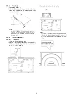
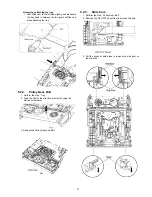
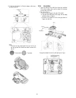
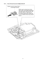
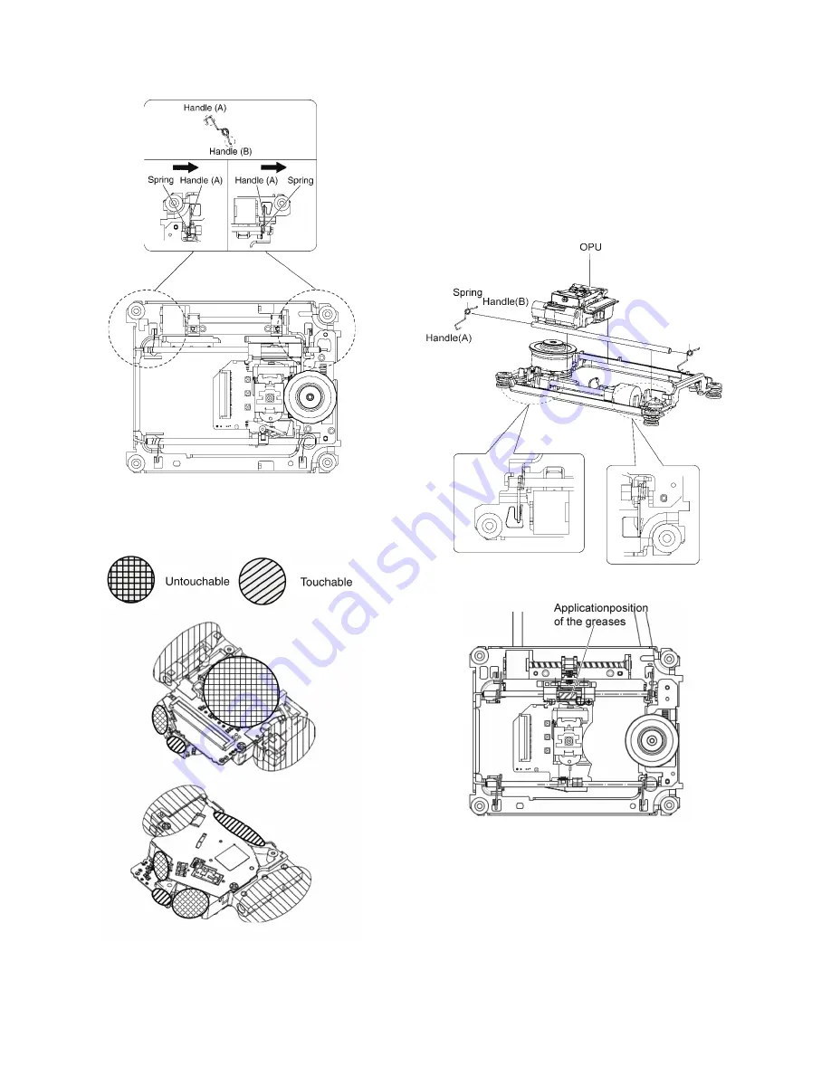
4. Press down the handle A of the two springs, and remove
the shaft with OPU.
Note:
In this action, finger stab needs to be put on. Do not
touch any parts other than the positions marked in the
Figure .
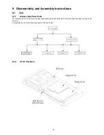
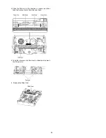
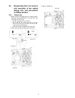
9.3.2.
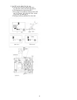
Assembly
1. Insert the shaft into the shaft hole of the base, install the
OPU to the auxiliary shaft, and then attach the nut piece
unit onto the screw stem.
2. Assembly of spring.
a. Insert the two springs to the ends of the shaft.
b. Then insert the handle (B) of the spring into the spring
holder(as shown in Figure).
c. Press down the handle (A) of the spring (as shown in
Figure) into the hole.
.
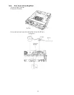
3. Apply the lubricants to the 1 point as shown in Figure.
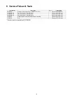
Summary of Contents for DMP-BD81PU
Page 2: ...2 ...
Page 3: ...3 ...
Page 8: ...8 2 2 Precaution of Laser Diode ...
Page 18: ...18 5 Location of Controls and Components ...
Page 40: ...40 9 2 5 Grease ...
Page 44: ...44 9 3 3 How to Clean the Lens of Optical Pick UP ...
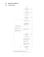
Page 45: ...45 9 4 Adjustment of BD Drive 9 4 1 Repair Flowchart ...
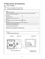
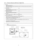
Page 49: ...49 10 1 2 Checking and Repairing of BD Drive and Digital P C B ...
Page 59: ...Model No DMP BD91GN 81PU 81GA 81GC 81GN 81GT BDT160GA 160GN 160GW BDT161GC PART LIST NOTICE ...
Page 60: ...Model No DMP BD91GN 81PU 81GA 81GC 81GN 81GT BDT160GA 160GN 160GW BDT161GC ABBREVIATION ...
Page 79: ...Model No DMP BD91GN 81PU 81GA 81GC 81GN 81GT BDT160GA 160GN 160GW BDT161GC Exploded View ...
Page 80: ...Model No DMP BD91GN 81PU 81GA 81GC 81GN 81GT BDT160GA 160GN 160GW BDT161GC Mechanism View ...
Page 81: ...Model No DMP BD91GN 81PU 81GA 81GC 81GN 81GT BDT160GA 160GN 160GW BDT161GC Packing View ...