10 Service Mode
10.1. (DVD) Self-Diagnosis and Special Mode Setting
10.1.1. (DVD) Self-Diagnosis Functions
Self-Diagnosis Function provides information for errors to service personnel by “Self-Diagnosis Display” when any error has
occurred.
U**, H** and F** are stored in memory and held.
You can check latest error code by transmitting [0] [1] of Remote Controller in Service Mode.
Automatic Display on FL will be cancelled when the power is turned off or AC input is turned off during self-diagnosis display is ON.
Error Code
Diagnosis contents
Description
Monitor Display
Automatic FL display
U30
Remote control code error
Display appears when main unit and remote
controller codes are not matched.
No display
“*” is remote controller code of the
main unit.
Display for 5 seconds.
U59
Abnormal inner temperature
detected
Display appears when the drive temperature
exceeds 70°C.
The power is turned off forcibly.
For 30 minutes after this, all key entries are
disabled. (Fan motor operates at the highest
speed for the first 5 minutes. For the
remaining 25 minutes, fan motor is also
stopped.) The event is saved in memory as
well.
No display
“U59 is displayed for 30 minutes.
U61
The unit is carrying out its
recovery process.
No display
U88
The unit is carrying out its
recovery process.
No display
U99
Hang-up
Displayed when communication error has
occurred between Main microprocessor and
Timer microprocessor.
No display
Displayed
is
left
until
the
[POWER] key is pressed.
H19
Inoperative fan motor
When inoperative fan motor is detected after
powered on, the power is turned off
automatically.
The event is saved in memory.
No display
No display
F00
No error information
Initial setting for error code in memory
(Error code Initialization is possible with error
code initialization and main unit initialization.)
No display
No display
F09
Serial Communication Error
between VHS Microprocessor
and Timer Microprocessor.
Please
confirm
Serial
Communication
terminal of Microprocessor.
NOTE:
If F09 appears just after updating Firmware,
pull off and insert AC plug, then it will
disappear.
No display
F34
Initialization error when main
microprocessor is started up
for program recording
When initialization error is detected after
starting up main microprocessor for program
recording,
the
power
is
turned
off
automatically.
The event is saved in memory.
No display
No display
F58
Drive hardware error
When drive unit error is detected, the event is
saved in memory.
No display
No display
F60
DVD module has not been
started.
Defect of Digital P.C.B.
Mode: No change
No display
38
DMR-ES35VGN / DMR-ES35VGC / DMR-ES35VGCS / DMR-ES35VEE
Summary of Contents for DMR-ES35VGN
Page 4: ...1 2 Caution for AC Mains Lead For GC only 4 DMR ES35VGN DMR ES35VGC DMR ES35VGCS DMR ES35VEE ...
Page 7: ...3 Precaution of Laser Diode 7 DMR ES35VGN DMR ES35VGC DMR ES35VGCS DMR ES35VEE ...
Page 10: ...6 Specifications For GN GC GCS 10 DMR ES35VGN DMR ES35VGC DMR ES35VGCS DMR ES35VEE ...
Page 11: ...11 DMR ES35VGN DMR ES35VGC DMR ES35VGCS DMR ES35VEE ...
Page 12: ... For EE 12 DMR ES35VGN DMR ES35VGC DMR ES35VGCS DMR ES35VEE ...
Page 13: ...13 DMR ES35VGN DMR ES35VGC DMR ES35VGCS DMR ES35VEE ...
Page 15: ...Audio Video cable 15 DMR ES35VGN DMR ES35VGC DMR ES35VGCS DMR ES35VEE ...
Page 17: ...8 2 Remote Control Operation For EE 17 DMR ES35VGN DMR ES35VGC DMR ES35VGCS DMR ES35VEE ...
Page 18: ...8 3 Main Unit Operation 18 DMR ES35VGN DMR ES35VGC DMR ES35VGCS DMR ES35VEE ...
Page 19: ...8 4 Main Unit Panel Display 19 DMR ES35VGN DMR ES35VGC DMR ES35VGCS DMR ES35VEE ...
Page 21: ...8 5 2 Discs for playing 21 DMR ES35VGN DMR ES35VGC DMR ES35VGCS DMR ES35VEE ...
Page 22: ...22 DMR ES35VGN DMR ES35VGC DMR ES35VGCS DMR ES35VEE ...
Page 23: ...23 DMR ES35VGN DMR ES35VGC DMR ES35VGCS DMR ES35VEE ...
Page 25: ...8 6 ABOUT DivX 25 DMR ES35VGN DMR ES35VGC DMR ES35VGCS DMR ES35VEE ...
Page 26: ...26 DMR ES35VGN DMR ES35VGC DMR ES35VGCS DMR ES35VEE ...
Page 27: ...27 DMR ES35VGN DMR ES35VGC DMR ES35VGCS DMR ES35VEE ...
Page 28: ...28 DMR ES35VGN DMR ES35VGC DMR ES35VGCS DMR ES35VEE ...
Page 29: ...29 DMR ES35VGN DMR ES35VGC DMR ES35VGCS DMR ES35VEE ...
Page 30: ...30 DMR ES35VGN DMR ES35VGC DMR ES35VGCS DMR ES35VEE ...
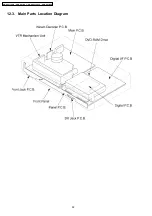
Page 52: ...12 3 Main Parts Location Diagram 52 DMR ES35VGN DMR ES35VGC DMR ES35VGCS DMR ES35VEE ...
Page 65: ...13 2 2 Notice for Replacing Capstan Motor 65 DMR ES35VGN DMR ES35VGC DMR ES35VGCS DMR ES35VEE ...
Page 67: ...67 DMR ES35VGN DMR ES35VGC DMR ES35VGCS DMR ES35VEE ...
Page 68: ...68 DMR ES35VGN DMR ES35VGC DMR ES35VGCS DMR ES35VEE ...
Page 86: ...DMR ES35VGN DMR ES35VGC DMR ES35VGCS DMR ES35VEE 86 ...
Page 94: ...DMR ES35VGN DMR ES35VGC DMR ES35VGCS DMR ES35VEE 94 ...
Page 96: ...96 DMR ES35VGN DMR ES35VGC DMR ES35VGCS DMR ES35VEE ...
Page 126: ...DMR ES35VGN DMR ES35VGC DMR ES35VGCS DMR ES35VEE 126 ...
Page 128: ...21 2 Casing Parts Mechanism Section 2 128 DMR ES35VGN DMR ES35VGC DMR ES35VGCS DMR ES35VEE ...
Page 129: ...21 3 VHS Mechanism Section 129 DMR ES35VGN DMR ES35VGC DMR ES35VGCS DMR ES35VEE ...
Page 130: ...21 4 Packing 130 DMR ES35VGN DMR ES35VGC DMR ES35VGCS DMR ES35VEE ...


