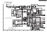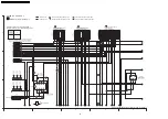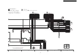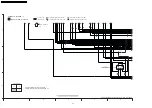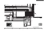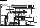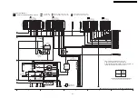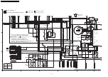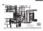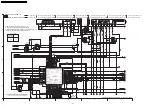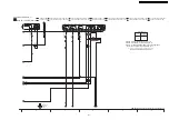
(All schematic diagrams may be modified at any time with
the development of new technology)
Note :
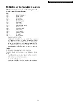
S1531
Safety TAB switch
S1532
MODE switch
S7701
V2D switch
S7702
STOP switch
S7703
SELECT switch
S7704
D2V switch
S7705
REC switch
S7706
OPEN/CLOSE switch
S7707
PLAY switch
S7801
CH DWN switch
S7802
REW switch
S7803
CH UP switch
S7806
POWER switch
S7810
FF switch
S7813
EJECT switch
·
Importance safety notice :
Components
identified
by
mark
have
special
characteristics important for safety. Furthermore, special
parts which have purposes of fire-retardant (resistors), high-
quality sound (capacitors), low-noise (resistors), etc. are
used. When replacing any of components, be sure to use
only manufacturer´s specified parts shown in the parts list.
Caution !
IC, LSI and VLSI are sensitive to static electricity.
Secondary trouble can be prevented by taking care during
repair.
·
Cover the parts boxes made of plastics with aluminium foil.
·
Put a conductive mat on the work table.
·
Ground the soldering iron.
·
Do not touch the pins of IC, LSI or VLSI with fingers directly.
18 Notes of Schematic Diagram
95
DMR-ES35VGN / DMR-ES35VGC / DMR-ES35VGCS / DMR-ES35VEE
Summary of Contents for DMR-ES35VGN
Page 4: ...1 2 Caution for AC Mains Lead For GC only 4 DMR ES35VGN DMR ES35VGC DMR ES35VGCS DMR ES35VEE ...
Page 7: ...3 Precaution of Laser Diode 7 DMR ES35VGN DMR ES35VGC DMR ES35VGCS DMR ES35VEE ...
Page 10: ...6 Specifications For GN GC GCS 10 DMR ES35VGN DMR ES35VGC DMR ES35VGCS DMR ES35VEE ...
Page 11: ...11 DMR ES35VGN DMR ES35VGC DMR ES35VGCS DMR ES35VEE ...
Page 12: ... For EE 12 DMR ES35VGN DMR ES35VGC DMR ES35VGCS DMR ES35VEE ...
Page 13: ...13 DMR ES35VGN DMR ES35VGC DMR ES35VGCS DMR ES35VEE ...
Page 15: ...Audio Video cable 15 DMR ES35VGN DMR ES35VGC DMR ES35VGCS DMR ES35VEE ...
Page 17: ...8 2 Remote Control Operation For EE 17 DMR ES35VGN DMR ES35VGC DMR ES35VGCS DMR ES35VEE ...
Page 18: ...8 3 Main Unit Operation 18 DMR ES35VGN DMR ES35VGC DMR ES35VGCS DMR ES35VEE ...
Page 19: ...8 4 Main Unit Panel Display 19 DMR ES35VGN DMR ES35VGC DMR ES35VGCS DMR ES35VEE ...
Page 21: ...8 5 2 Discs for playing 21 DMR ES35VGN DMR ES35VGC DMR ES35VGCS DMR ES35VEE ...
Page 22: ...22 DMR ES35VGN DMR ES35VGC DMR ES35VGCS DMR ES35VEE ...
Page 23: ...23 DMR ES35VGN DMR ES35VGC DMR ES35VGCS DMR ES35VEE ...
Page 25: ...8 6 ABOUT DivX 25 DMR ES35VGN DMR ES35VGC DMR ES35VGCS DMR ES35VEE ...
Page 26: ...26 DMR ES35VGN DMR ES35VGC DMR ES35VGCS DMR ES35VEE ...
Page 27: ...27 DMR ES35VGN DMR ES35VGC DMR ES35VGCS DMR ES35VEE ...
Page 28: ...28 DMR ES35VGN DMR ES35VGC DMR ES35VGCS DMR ES35VEE ...
Page 29: ...29 DMR ES35VGN DMR ES35VGC DMR ES35VGCS DMR ES35VEE ...
Page 30: ...30 DMR ES35VGN DMR ES35VGC DMR ES35VGCS DMR ES35VEE ...
Page 52: ...12 3 Main Parts Location Diagram 52 DMR ES35VGN DMR ES35VGC DMR ES35VGCS DMR ES35VEE ...
Page 65: ...13 2 2 Notice for Replacing Capstan Motor 65 DMR ES35VGN DMR ES35VGC DMR ES35VGCS DMR ES35VEE ...
Page 67: ...67 DMR ES35VGN DMR ES35VGC DMR ES35VGCS DMR ES35VEE ...
Page 68: ...68 DMR ES35VGN DMR ES35VGC DMR ES35VGCS DMR ES35VEE ...
Page 86: ...DMR ES35VGN DMR ES35VGC DMR ES35VGCS DMR ES35VEE 86 ...
Page 94: ...DMR ES35VGN DMR ES35VGC DMR ES35VGCS DMR ES35VEE 94 ...
Page 96: ...96 DMR ES35VGN DMR ES35VGC DMR ES35VGCS DMR ES35VEE ...
Page 126: ...DMR ES35VGN DMR ES35VGC DMR ES35VGCS DMR ES35VEE 126 ...
Page 128: ...21 2 Casing Parts Mechanism Section 2 128 DMR ES35VGN DMR ES35VGC DMR ES35VGCS DMR ES35VEE ...
Page 129: ...21 3 VHS Mechanism Section 129 DMR ES35VGN DMR ES35VGC DMR ES35VGCS DMR ES35VEE ...
Page 130: ...21 4 Packing 130 DMR ES35VGN DMR ES35VGC DMR ES35VGCS DMR ES35VEE ...


