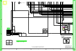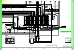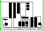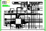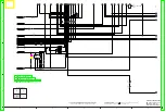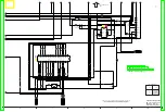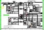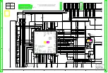
C7701
0.1
D7706
B3AAA0000752
R7715
270
D7704
B3ABA0000595
R7708
680
D7702
B3ADA0000173
R7705
390
D7703
B3ACA0000273
R7706
390
S7704
1500
R7704
S7711
S7706
S7705
S7707
1500
R7714
R7707
2200
S7702
S7703
1500
R7703
2
1
3
B3RAD0000122
7
9
10
8
4
5
1
3
2
6
12
11
K1KA12B00129
PP7701
Q7706
100K
R7718
100K
R7716
220
R7710
Q7702
Q7703
100K
R7721
Q7704
100K
R7719
D2V
OPEN/CLOSE
V2D
PLAY
SELECT
STOP
DVD
VHS
SD
REC
DUB
SD_I
IR
AD5V
KEY2
KEY1
KEY3
VHS_LED
SD_LED
DVD_LED
DUB_LED
GND
GND
SST6V
DMR-ES45VP/ES46VP
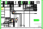
Front (R) Schematic Diagram
10
9
8
7
6
5
4
3
2
1
SLIGHTLY DIFFERNT OR AMENDED SINCE THIS DRAWING WAS PREPARED.
THE CORRECT PART NUMBER IS SHOWN IN THE PARTS LIST,AND MAY BE
NOTE:DO NOT USE THE PART NUMBER SHOWN ON THIS DRAWING FOR ORDERRING.
Summary of Contents for DMR-ES45VP
Page 7: ...3 Service Navigation 3 1 Service Information 4 Specifications 7 ...
Page 68: ...10 13 Main P C B 1 Disconnect 5 Connectors 2 Remove 2 Screws A and remove Main P C B 52 ...
Page 70: ...11 1 2 Checking and Repairing of Main P C B 54 ...
Page 71: ...11 1 3 Checking and Repairing of RAM Digital P C B Module 55 ...
Page 73: ...11 2 3 Items that should be done after replacing parts 57 ...
Page 74: ...58 ...
Page 75: ......
Page 87: ...17 1 2 Casing Parts Mechanism Section 2 70 ...
Page 88: ...17 1 3 VHS Mechanism Section 71 ...
Page 89: ...17 1 4 Packing Accessories Section 72 ...
Page 111: ...C11701 F2A1A2220055 10V 2200U 1 94 ...
Page 123: ......
Page 124: ......
Page 132: ...1 4 2 4 3 4 4 4 DMR ES45VP ES46VP Main P C B VEPV0054BT 4 4 Section Location Map REAR FRONT ...

